Baling presses compress cardboard, paper, plastic film, PET bottles and scrap metal into transportable bales. The part that produces the press force is the hydraulic cylinder; what feeds the cylinder is a hydraulic power unit: oil tank, pump, valve block and the electric motor that turns the pump. When replacing a motor or installing a new unit, often only the power is asked about. Yet in a hydraulic unit, what determines the motor is the pump's pressure and flow, the structure of the press cycle, how the motor is connected to the pump and the direction of rotation. In this article we cover these topics using the 4-pole cast iron models HEM Motor has on sale.
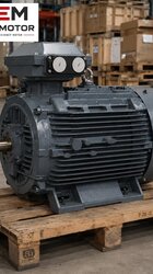
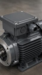
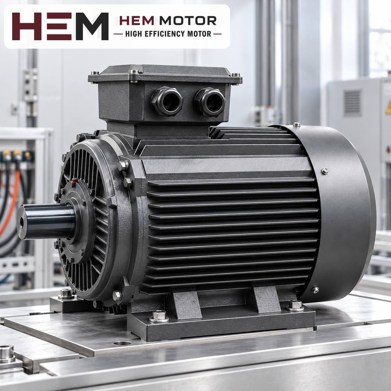
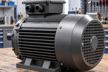
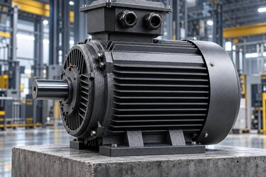
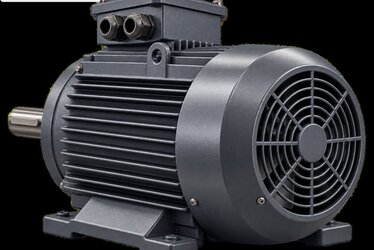
In a hydraulic unit, the motor's direction of rotation and pump connection are checked before commissioning (representative image).
Where does the motor power come from in a hydraulic unit?
The power the pump demands at the shaft depends on the product of the pressure and flow it delivers. The approximate expression used in practice is: hydraulic power (kW) ≈ pressure (bar) × flow (l/min) / 600. This value is the hydraulic power at the pump outlet; when the losses of the pump and circuit are added, the power required from the motor rises above it. How large the losses are depends on the pump type and circuit design; that is why the calculation should be completed with the values given by the pump manufacturer.
In baling presses the cycle does not consist of a single fixed point. The cylinder first advances quickly without load (high flow, low pressure), slows down and compresses when it meets the material (low flow, high pressure), then retracts. What stresses the motor is the largest pressure × flow product among these phases; multiplying the highest pressure by the highest flow at the same time can lead to an unnecessarily large motor.
Double-pump and load-sensing circuits
Double pump (high-low): During rapid advance both pumps deliver together; when pressure rises the large pump is unloaded and the small pump does the compressing. This keeps the motor in a similar power band in both phases.
Variable displacement pump: As pressure rises, the pump reduces its flow automatically. The motor power is determined by the pump's set power limit.
Single fixed displacement pump: The simplest circuit; the motor must be powerful enough to deliver full flow at the highest pressure.
Determining the power by looking only at the press tonnage without knowing which circuit you have is not correct. In an existing unit, the most reliable information is the old motor's nameplate and the pump's type plate.
Why mostly 1,500 rpm?
Most gear and vane pumps are designed for a speed range in which they can run without cavitation on the suction side; this is why 4-pole motors, i.e. those with a synchronous speed of 1,500 rpm, are common in hydraulic units. Although a 3,000 rpm motor may seem to get twice the flow from the same pump, it can exceed the speed the pump allows and create noise and wear at the suction. Before changing the number of poles of the motor in an existing unit, check the pump manufacturer's speed limit.
The rated speed on the nameplate is slightly lower than the synchronous speed. For example, the rated speed of the 132M-4 model is 1,460 rpm; this value is used when calculating pump flow.
Pump connection and mounting arrangement
In hydraulic units, the motor is usually connected to the pump through a pump mounting bracket (bell housing) and a flexible coupling. The bell housing seats on the motor flange on one side and on the pump flange on the other; the coupling joins the two shafts. Three matches are important in this arrangement:
Motor flange and bell housing: A flange-mounted (B5) or foot-and-flange-mounted (B35) motor is used. Mounting arrangements are offered according to the frame and the flange size is confirmed with the order; the name "B5" alone does not show that the bell housing will fit.
Shaft and coupling hub: The shaft diameter and keyway change together with the motor's frame size. If the existing coupling hub does not fit the new shaft, a new hub is needed.
Vertical mounting: In some units the motor stands vertically (V1) on top of the tank and the pump hangs into the tank. Vertical mounting options are also offered according to the frame; state the motor's position in the order.
Most gear pumps are unidirectional. A pump running in reverse does not deliver oil and can be damaged in a short time. In a three-phase motor, the direction of rotation is reversed by swapping two of the supply phases. For this reason, before connecting the new motor to the pump, the direction should be checked with a short trial run and compared with the arrow on the pump body.
Having the pump unloaded at start-up relieves the motor. In many units an unloading valve sends the pump's flow to the tank until the motor reaches operating speed; star-delta starting works without problems in this case. Motors rated 400/690 V are connected in delta on a 400 V network and are therefore suitable for star-delta starting. If the pump has to start under pressure, state this in the order.
During the cycle the motor usually runs continuously; while the press waits, the pump is unloaded. In some units, however, the motor is stopped and restarted for every bale. If the number of starts per hour is high, the motor winding heats up; this information is important for a correct selection. Whether it is better to leave the motor running or to stop it during long intervals when the pump is idle is assessed according to the number of starts.
Our three-phase series are suitable for speed control with a frequency inverter; for long periods at low speed with full torque an external fan may be required, and if the cable between drive and motor is long, a dv/dt or sine filter is considered; these conditions are stated in the order.
Example models seen in baling press units
The cast iron models below are examples of the power range encountered in the hydraulic units of small and medium baling presses. Your press's requirement is determined by the pump and circuit design; the rows here should not be read as a list of recommendations.
The listed motors have IP55 protection and class F insulation; the supply is defined as 400/690 V (Δ/Y) at 50 Hz. The 132S and 132M have the same shaft height but different frame lengths; in units connected by flange this difference is often not a problem, while in units also fixed by the feet the foot spacing is checked. Other information on hydraulic applications is on the electric motors for hydraulic pumps page.
Hypothetical example: renewing the motor of a vertical baler
This example has been constructed to show the order of checks; it is not a real application. Suppose that in the hydraulic unit of a vertical cardboard baler in a recycling depot, the winding of a motor whose nameplate reads 7.5 kW and 1,450 rpm has burned out. The motor is connected to a gear pump via a bell housing and coupling.
Power and speed: The nameplate indicates a 4-pole motor. The rated speed of the 132M-4 cast iron model is 1,460 rpm; the pump flow practically does not change.
Connection: The old motor's flange type and the flange size on which the bell housing seats are noted; this information is given in the order so that the flange fit is confirmed. Whether the coupling hub fits the shaft diameter is checked against the catalogue.
Cause of failure: The reason for the burned winding is investigated: a clogged filter or a relief valve whose setting has drifted may have kept the pump at high pressure continuously; the number of starts per hour may be very high.
Commissioning: The direction of rotation is checked with a short run before the pump is connected. Then the current is measured during compression; if the current stays continuously above the 14.3 A rated value, the relief valve setting and circuit are reviewed.
Information needed for the order
A clear photo of the removed motor's nameplate
The pump's type plate; if known, the operating pressure and flow
Connection type: bell housing and coupling, mounting arrangement (B5, B35, vertical V1) and flange size
Starting method, supply voltage and approximate number of starts per hour
The environment where the unit is located (dust, outdoors, temperature)
You can see motors that may suit your hydraulic unit, together with their prices, on our shop page. If you would like to ask for an equivalent using your current motor's nameplate, send the photo via the find an equivalent motor from the nameplate page; for questions about the pump and circuit, write to us.
HEM Motor Models Related to This Article
The cards show example models related to the topic. A suitable motor is not chosen by power alone: compare speed, voltage, mounting, shaft and connection dimensions on the product page; if unsure, send a photo of the existing motor’s nameplate on WhatsApp.
There is no single "seed cleaner motor" in a seed cleaning and grading machine; the machine consists of several motors, each carrying a different load: the drive that shakes the si... More Details
If a compressor motor cannot start against tank pressure, the cause is usually not the motor's power. The most common causes are a faulty unloader or check valve, low supply voltag... More Details
On a dough kneading machine, the spiral or fork arm folds the dough with a slow but powerful movement; on most models the bowl also turns about its own axis. This need for low spee... More Details
On a circular saw, the toothed blade cuts the material at dozens of revolutions per second; on most machines the blade is attached to the motor shaft or to a shaft very close to th... More Details
On a wood band saw, the blade that does the cutting runs over two large wheels; the motor usually turns the lower wheel through a belt and pulley. Thanks to this arrangement, a ban... More Details
On a bridge-type marble cutting machine, the main motor is the part that turns the diamond blade and carries the heaviest load throughout the cut. When this motor has to be replace... More Details
We use necessary and optional cookies to improve your experience, enhance content and analyse traffic. Under the GDPR, optional (analytics/marketing) cookies are only used with your explicit consent. Please choose your preference below.
Cookie Policy
 English
 Français
 Türkçe
 Español
 Русский