English
 Français
 Türkçe
 Español
 Русский

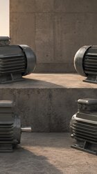

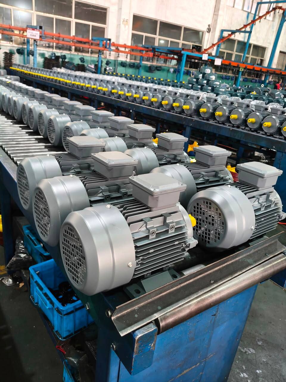

When moving from a sample motor to series orders, the safest way to keep technical compatibility is to turn the approved sample into a written reference record and compare every series order with it. Matching power and speed is not enough; the frame material, IEC frame code, mounting arrangement, flange size and voltage connection must stay the same as well. If one of these changes silently, the problem usually appears on the machine assembly line, when the motor does not fit.
This article is for manufacturers who build their own machines and buy the motor as a component. It is not about choosing a motor for a single machine, but about supplying the same motor repeatably for dozens of machines.
Which information should you freeze when the sample is approved?
When the sample motor is fitted to the trial machine and run, the team actually holds a design decision. That decision contains more information than the motor nameplate and the order line. Write at least the following into the reference record:
- Model code and power: e.g. 100L2-4, 3 kW. The code describes the IEC frame and the number of poles together.
- Frame material: aluminium or cast iron. It is not part of the code, so it must be written separately.
- Mounting arrangement and flange: B3, B5, B14, B34, B35 or vertical; if flanged, the size of the part it mates with on the machine.
- Voltage and connection: the voltage on the nameplate (230/400 V or 400/690 V) and the connection used on your machine (star or delta).
- Starting method: direct-on-line, star-delta or frequency inverter.
- Layout details: the position of the terminal box on the machine, the cable entry direction and the part the shaft end connects to (coupling, pulley, gearbox input).
Instead of writing dimensions (shaft diameter, flange, foot hole spacing) into the record by hand, note the name and revision of the relevant 2D technical drawing. That way, any discussion about dimensions is based on the same document, not on two people reading a ruler.
Why is the model code alone not enough?
At HEM Motor, the model code does not change with the frame material. For example, the code 112M-4 is used for both the aluminium and the cast iron frame model with 4 kW and a rated speed of 1,450 rpm; the electrical values are identical. If purchasing writes only "112M-4" on the order, the motor delivered may not be made of the same material as the sample. When the frame material changes, the motor's weight and appearance change; if your machine's supporting structure, cover design or customer expectations are sensitive to this, the frame must be stated on the order line.
Another limit is the power range. Aluminium frame models cover 0.25–11 kW and cast iron frame models cover 0.55–355 kW. So a 0.25 or 0.37 kW sample cannot be switched to cast iron for the series, because the standard list on sale has no equivalent; if this need exists, it should be asked about separately.
What changes when the power changes within a machine family?
In series production, the same machine comes in small and large versions. Approving the sample at 3 kW and moving to 4 kW for the large version seems natural, but more than the power changes at this step:
| Feature | 3 kW, 4-pole | 4 kW, 4-pole |
|---|---|---|
| Model code | 100L2-4 | 112M-4 |
| IEC frame | 100L | 112M |
| Rated speed | 1,450 rpm | 1,450 rpm |
| Voltage | 230/400 V (Δ/Y) | 400/690 V (Δ/Y) |
| Connection on a 400 V supply | Star (Y) | Delta (Δ) |
Because the frame moves from 100L to 112M, the foot and flange dimensions differ; the base and motor plate must be drawn separately for each version. The difference on the voltage side is easier to miss. Star-delta starting on a 400 V supply requires the motor to be connected in delta on that supply; the 4 kW model rated 400/690 V is therefore suitable for it, while the 3 kW model rated 230/400 V is connected in star at 400 V and is not suitable for star-delta starting. The panel diagram and the terminal connection instruction should be prepared separately for each version.
Mounting and flange: the most common deviation
The item that causes the most trouble in series orders is the flange. Calling a flange simply "B5" or "B14" does not prove that it matches the connection size on your machine. Mounting options (B3, B5, B14, B34, B35 and vertical V1/V3/V5/V6/V15) are offered according to the frame and the flange size is confirmed with the order; details are summarised in the mounting arrangements question. Match the size of the flange used on the sample with the 2026 technical and product catalogue, write it into the reference record and repeat the same wording in every series order.
You can review suitable models from the standard range and current prices on the buy electric motors page.