English
 Français
 Türkçe
 Español
 Русский

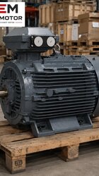

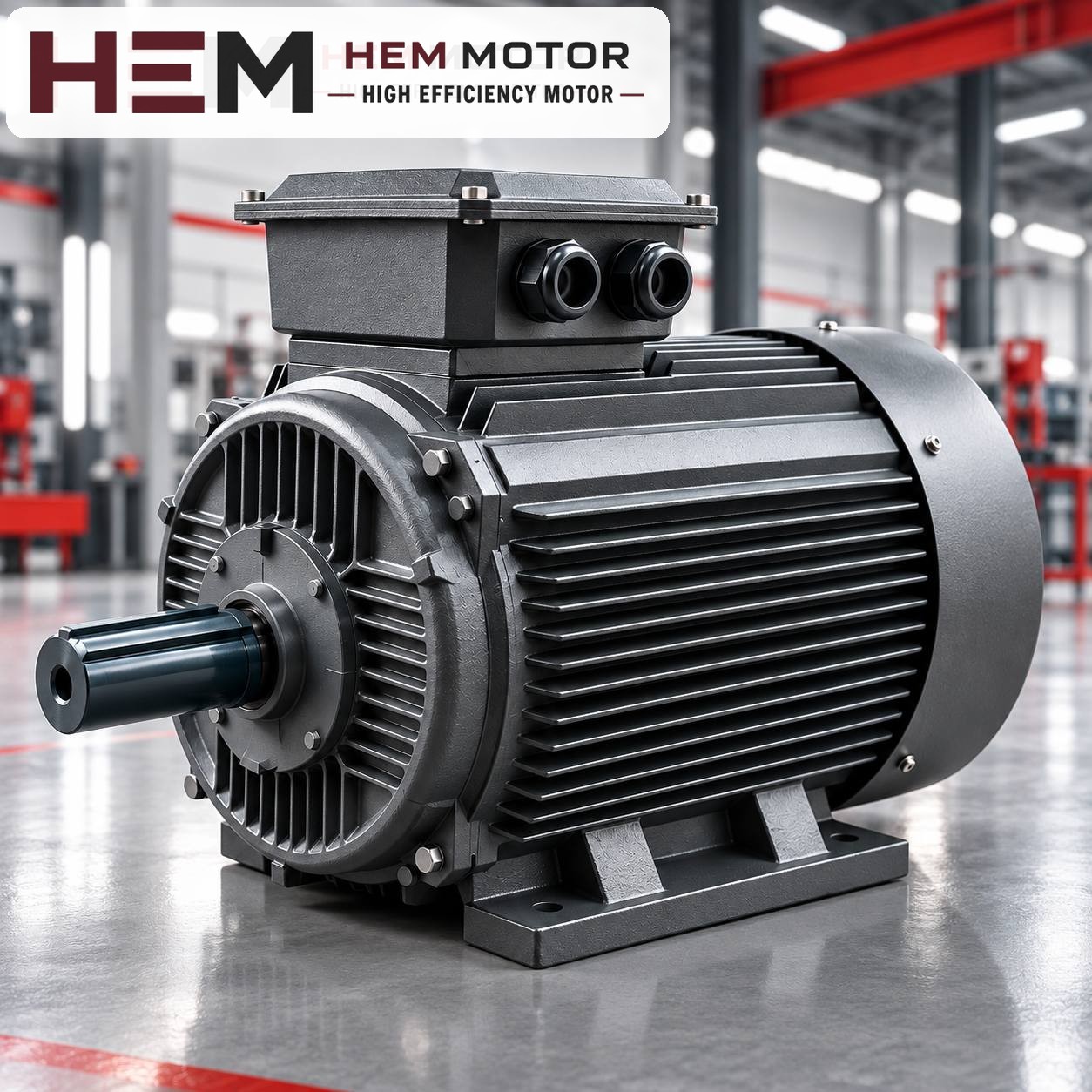

In a flour mill, the roller mill is the machine that breaks and reduces the wheat step by step; each roll pair's shaft must turn at a speed defined in the mill's flow sheet. In most plants that speed is set not directly by the motor but by the belt-and-pulley drive between the motor and the roller mill. That is why, when a roller mill motor is replaced, looking only at kilowatts is not enough: the motor's rated speed, the pulley diameters and the load the belt places on the motor shaft must be considered together. Below we go through these three topics in order, using the cast iron models HEM Motor has on sale.

Who sets the roll speed: the motor or the pulley?
The roller mill manufacturer specifies certain shaft speeds for the machine's fast and slow rolls. The speed difference between the two rolls is usually fixed by a gear or belt arrangement inside the machine; the motor's job is to deliver the right speed and sufficient torque to the input shaft of the fast roll. The pulley ratio between the motor and the roller mill is the final link that sets this input speed.
The basic relationship is simple: the speed of the roller mill pulley equals the motor speed multiplied by the ratio of the pulley diameters. As a formula, nroll = nmotor × dmotor pulley / droll pulley. Remember that the belt slips slightly and that the calculation uses effective diameters; the result is an approximate value, and the final setting is verified on site with a tachometer.
The practical consequence of this relationship is this: if the rated speed of the old motor in the mill differs from that of the new motor, the roll speed changes too. For example, when a model with a rated speed of 1,465 rpm replaces a motor whose nameplate reads 1,450 rpm, the roll turns about one percent faster with the same pulleys. This small difference is usually within tolerance; however, fitting a 1,000 rpm model in place of a 1,500 rpm motor means an unacceptable drop in speed unless the pulley ratio is changed.
Cast iron models that stand out on the mill side
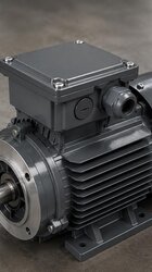
In flour mills, roller mill drives are mostly 4-pole motors, that is, motors with a synchronous speed of 1,500 rpm; the pulley ratio is calculated for this speed. The table below shows three cast iron models on sale on the website that fall within the power range often seen in roller mill drives. The power required depends on roll length, grinding passage and capacity; the table is not a recommendation but a summary of the recorded values.
| Model code | Power | Synchronous / rated speed | IEC frame | Rated current (400 V) | Rated torque |
|---|---|---|---|---|---|
| 160M-4 | 11 kW (15 HP) | 1,500 / 1,465 rpm | 160M | 20.4 A | 71.7 Nm |
| 160L-4 | 15 kW (20 HP) | 1,500 / 1,465 rpm | 160L | 27.3 A | 97.8 Nm |
| 180M-4 | 18.5 kW (25 HP) | 1,500 / 1,470 rpm | 180M | 33.5 A | 120.2 Nm |
All three models are IP55, have class F insulation and run on a 400/690 V (Δ/Y), 50 Hz supply; on a 400 V network they are connected in delta. The 160M and 160L have the same shaft height, but their frame length and foot hole spacing differ; the 180M is one frame size up. Check whether it fits the motor base or tensioning rail under the roller mill using the 2D technical drawings. Other information for the sector is collected on the flour mill electric motors page.
The load placed on the motor shaft by a belt drive
Unlike a coupling drive, in a belt drive the motor shaft does not carry only the turning moment; the belt tension applies a sideways force to the shaft. This radial load is the factor that stresses the motor's front bearing the most and is one of the common reasons for early bearing noise after a replacement.
Conditions that increase the radial load
- A motor pulley that is too small: To transmit the same torque through a small diameter, the belt has to pull harder. Rather than shrinking the motor pulley excessively to achieve the pulley ratio, enlarging the roll pulley is usually the healthier choice.
- Fitting the pulley at the end of the shaft: The further the pulley sits from the shaft shoulder, the greater the effect of the force on the bearing. The pulley should be seated as close to the frame as the shaft length allows.
- An overtightened belt: Overtightening the belt to prevent slipping moves the problem to the bearing. Tension is set according to the belt manufacturer's recommendation.
- Misalignment: If the motor pulley and the roll pulley are not in the same plane, the belt wears at the sides and vibration increases.
Whether the pulley hub fits the new motor's shaft is a separate check. Shaft diameter and key size vary with the frame code; compare these dimensions using the catalogue and technical drawings, not by guesswork.