English
 Français
 Türkçe
 Español
 Русский

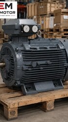
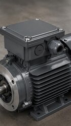


Feed mixers turn ground grain, oilseed meal, mineral additives and liquid ingredients into a homogeneous mix. In horizontal-shaft paddle or ribbon mixers, the mixing shaft turns at a low speed of a few tens of revolutions per minute. Since an electric motor turns at around 1,000, 1,500 or 3,000 rpm, there is always a speed reducer in between: most often a gear reducer, sometimes with a belt and pulley or chain stage added in front of it. This article looks at what to check on the motor side when choosing a motor suited to a geared drive on a feed mixer, what the reducer requires, and which information is needed with the order.
Division of work between motor and reducer in a mixer
In a geared drive the motor produces the power and the reducer lowers the speed and increases the torque. The torque at the reducer output is found roughly by multiplying the motor torque by the ratio and deducting the reducer losses. A mixer being "powerful" therefore does not depend on a large motor alone; a reducer with the right ratio makes it possible to obtain high torque at the mixing shaft with a motor of reasonable power.
The most common mistake in motor selection is confusing the speed of the mixing shaft with the motor speed. The mixer speed is set by the reducer ratio chosen by the machine manufacturer. Fitting a 1,000 rpm motor in place of a 1,500 rpm motor while the reducer stays the same slows the mixer by one third and increases the torque at the motor shaft at the same power. Mixing time gets longer and mix quality may change. Conversely, a higher-speed motor speeds up the mixer; it increases wear on the paddles and the trough and may crush the product. The motor speed is therefore chosen according to the input speed on the reducer nameplate.
What to read on the reducer nameplate
- Ratio (i): The ratio of input speed to output speed. Dividing the motor speed by this ratio gives the mixer speed.
- Input speed and input power: Shows which motor speed and power the reducer was selected for. Motor power must not exceed the input power permitted by the reducer.
- Service factor: The margin the reducer manufacturer provides for shock loads such as a mixer. This margin protects the reducer; it is not the value that determines the motor power.
- Connection type: Whether the motor is connected by flange (with an IEC adaptor) or on a separate base with a coupling.
How the motor is connected to the reducer
Three typical connections are seen on feed mixers. Which one is used directly determines the mounting arrangement of the motor to be ordered.
- Direct flange connection: The motor sits on the reducer's input adaptor with its B5 or B14 flange; the motor shaft fits into the reducer input shaft with a key. In this arrangement, the motor's IEC frame size, flange size and shaft diameter must match the reducer adaptor exactly. For the same frame code, B5 and B14 flange dimensions differ; the same name does not mean compatibility.
- Separate base with coupling: The motor is foot-mounted (B3) on a common baseplate next to the reducer, with a flexible coupling in between. In this arrangement the shaft height, the foot hole spacing and the coupling alignment are important.
- Belt and pulley + reducer: The motor turns the reducer input shaft through a belt. The pulleys form an additional speed stage and allow fine adjustment. Here belt tension puts a side load on the motor's front bearing; fitting the pulley as close to the shaft shoulder as possible relieves the bearing.
Mounting arrangements are offered according to the frame and the flange size is confirmed with the order; the options are summarised in the mounting arrangements question. The shaft and flange dimensions to be matched with the reducer are given by frame size in the 2D technical drawings. For a general overview of geared applications, see the motors for reducers page.
The load character specific to a mixer
A feed mixer is not a smooth load like a pump or a fan. The following characteristics must be discussed when choosing the motor.
- Full-load start: In many plants the mixer works in batches: it is filled, mixed and emptied. After a power cut or an emergency stop, the machine may have to be restarted while full. In this case the motor has to set in motion a heavy mass at rest; this is the moment when the starting torque requirement is highest.
- Changes in density and moisture: When molasses, oil or water is added, the mix becomes heavier and the resistance on the paddles rises. As the recipe changes, the motor current changes too.
- Pulsating load: As the paddles move through the mix, the load rises and falls periodically. This fluctuation creates fatigue in the motor, the coupling and the reducer gears.
- Dust: Heavy dust is generated while dry ingredients are loaded; the motor's cooling fins and fan cover should be cleaned regularly.
On machines where a full-load start is possible, direct-on-line starting or a frequency inverter is often preferred. With star-delta starting, torque drops in the star position, so a full mixer may not reach sufficient speed in star. A frequency inverter softens the start and also allows the mixing speed to be adjusted to the recipe; however, long operation at full torque at low speed reduces the cooling provided by the motor's own fan. The general rule is explained in the inverter use question; if such operation is planned, the need for a separate fan is discussed with the order.