English
 Français
 Türkçe
 Español
 Русский

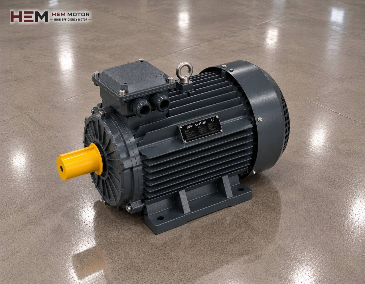
Rubber processing starts by mixing raw rubber with carbon black, oil and chemicals; the compound is worked on rolls, turned into sheet on a calender or into profile on an extruder, and finally vulcanised in a press or an oven. Along the line, the load on the motors is clearly heavier than on plastics machines. The general framework of the sector is on the plastic and rubber processing motors page; here we look at the drives in rubber machines one by one.

The load that rubber compound puts on the motor
Rubber has a much higher viscosity than plastic melt, and its behaviour changes with temperature. Cold compound is hard and resistant; as it is worked it warms up, softens and the torque on the motor falls. As soon as fillers such as carbon black are added, torque rises again. So in rubber machines the load draws a distinct curve from the start to the end of a batch, and the motor is sized for the steepest point of that curve.
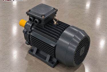
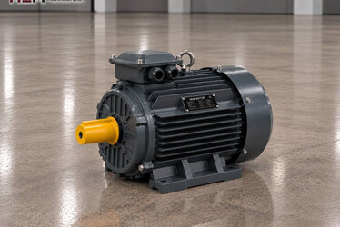
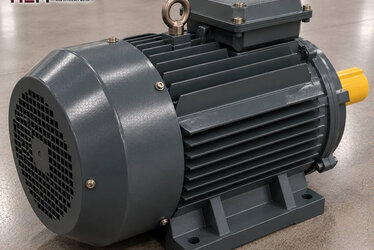
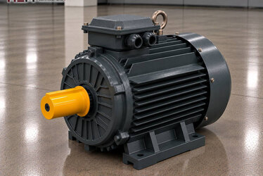
Most drives run at low speed. Rolls, mixer rotors and extruder screws turn slowly, and the speed difference is taken up by a gearbox or gear case. On the motor side, the most common choice is a 4-pole or 6-pole cast iron motor.
Internal mixer (Banbury type)
In an internal mixer two rotors turn in opposite directions in a closed chamber, and a ram from above presses the compound between them. Rubber and fillers turn into a uniform mix within a few minutes; then the door below opens and the batch is discharged. For the motor this is a heavy load cycle repeated every few minutes: torque peaks at loading, decreases as the mix warms up and drops close to zero at discharge.
These machines are the largest drives in a rubber plant, and at high power the motor selection is based on the machine builder's data. Our catalogue covers three-phase motors up to 355 kW; models of 75 kW and above have a service factor of 1.15, which is a safety margin and should not be used as a reason to choose a smaller motor. On large mixers, starting and supply load are usually handled with a soft starter or a frequency inverter; the plant design makes that decision.
Two-roll open mill and calender
In a two-roll mill two cylinders side by side turn towards each other at different speeds. The speed ratio between them (friction) works the compound by squeezing and shearing it. The rolls can be driven by one motor through a gear case or each by its own drive. Because the operator feeds the compound onto the rolls by hand, stopping the rolls in a very short time on emergency stop is a basic requirement of machine safety. The braking arrangement belongs to the machine's safety design; if a brake motor is required, state it in your order.
A calender consists of three or four rolls and forms rubber into sheet of a set thickness or coats it onto fabric. What matters here is speed matching between the rolls; product thickness and tension depend on it. The main rolls run on inverter-driven motors, and winders and take-off rollers on smaller drives. Some lines that need precise speed matching use servo drives; servo motors are not included in HEM Motor's 2026 catalogue.
Rubber extruder, cutting and vulcanisation
A rubber extruder pushes compound continuously through a die in the production of seals, hoses and profiles. Unlike a plastics extruder, the screw is shorter and the material is processed at lower temperature with higher resistance. So the screw motor carries high torque at low speed and is driven by an inverter for speed adjustment. As the load pattern of a plastics extruder is covered on a separate sub-page, here we only highlight this difference.
Most vulcanising presses are hydraulic: the force closing the mould is produced by cylinder and oil pressure, and the electric motor only turns the hydraulic pump. Motor selection is made by pump flow and working pressure; for details see the electric motors for hydraulic pumps page. Rubber bale cutters also mostly use a hydraulic blade. If a cutter has a mechanical drive, the load is short and impact-like.
Gearbox, inverter and hot environment
On roll and mixer drives the motor is connected to the gearbox either through a coupling or directly by a flange. Foot-mounted B3 and foot-and-flange B35 are the most common arrangements; depending on frame size, B5, B14, B34 and vertical V1, V3, V5, V6, V15 versions are also available, and flange and shaft dimensions are finalised at the order stage. For gearbox selection the electric motors for gearboxes page is helpful.
In most plants the speed of mills, calenders and extruders is adjusted by inverter; our three-phase series are compatible with this use. Because heavy load at low speed can last long on rolls, cooling the motor with a separate fan and using an output filter when the panel is far away may come up; we discuss both at the quotation stage. The general explanation is on the inverter compatible electric motors page.
In the mixing area fine carbon black dust spreads everywhere and can form a conductive, oily layer on the motor surface. The fan cover and fins should be cleaned regularly and the terminal box kept closed. For motors working next to hot rolls, a PTC or PT100 sensor can be requested to monitor winding temperature.
Example motors by machine
| Machine | Load on the motor | What to check | Example HEM model |
|---|---|---|---|
| Laboratory or small two-roll mill | Geared, varying, frequent stops | Roll diameter, braking arrangement | 11 kW 160M-4 (1,465 rpm) |
| Production two-roll mill | Heavy at low speed, with friction ratio | Friction ratio, gearbox input | 45 kW 280S-6 (985 rpm) |
| Internal mixer | Peak load repeated each batch | Batch volume, starting, supply | 90 kW 315M-6 (988 rpm, SF 1.15) |
| Rubber extruder (seals, hoses) | High torque at low speed, inverter | Screw diameter, speed range, cooling | 30 kW 200L-4 (1,475 rpm) |
| Vulcanising press hydraulic unit | Pump drive, pressure cycle | Pump flow and pressure | 7.5 kW 132M-4 (1,460 rpm) |
The values are for example only. Actual power and speed are determined by the machine builder's data, batch size, compound type, gear ratio and running time. The existing motor's nameplate is always the first reference.
Information we need before ordering
It is enough to write to us: machine type (mill, calender, mixer, extruder, press), motor power (kW) and speed (rpm), plant voltage, mounting type and gearbox connection, use of an inverter or brake, and quantity. You can send a photo of the old motor's nameplate as described on the send a motor nameplate page.
You can browse priced models in the buy electric motors shop and reach us by WhatsApp and phone via the contact page.
Frequently Asked Questions
Why does the mill motor draw so much current at the start of a batch?
Cold rubber is hard and resistant; as it warms up it softens and torque falls. High current at the start of the batch is therefore normal, but check that the protection setting suits this peak and that the compound is pre-warmed correctly.
Can I choose a smaller motor for an internal mixer and rely on the service factor?
No. The service factor is a safety margin for unexpected loading; it is not used to reduce the design power. The motor power should be selected according to the value given by the machine builder.
Does a standard motor give enough precision on calender rolls?
A standard motor driven by a vector-controlled inverter is sufficient for many calenders. On lines that need very tight thickness tolerances, the control structure should be decided together with the line builder.
Does carbon black dust harm the motor?
The dust builds up on the motor surface and weakens cooling, and because it is conductive it must not get into the terminal box. Regular cleaning and a tightly closed terminal box reduce this risk.