English
 Français
 Türkçe
 Español
 Русский

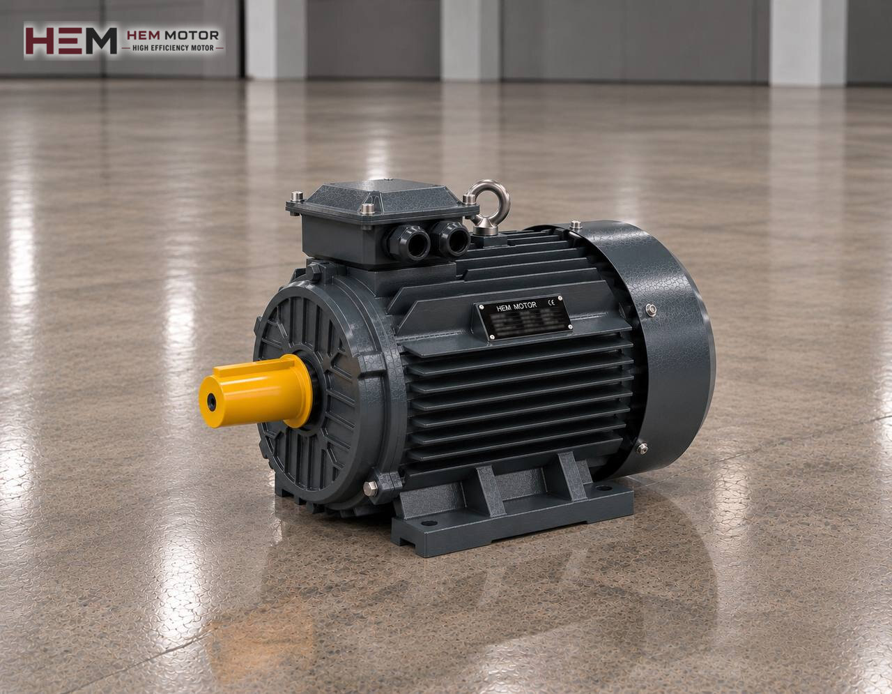
On a hydraulic plastic injection moulding machine, the forces that close the mould, push the melt into the mould and eject the part all come from oil pressure; the electric motor turns the hydraulic pump that creates this pressure. This page is a sub-section of plastic and rubber processing motors and explains how the pump motor is loaded during the injection cycle. The general calculation for selecting a hydraulic pump motor is on the hydraulic pump electric motors page.

The load the pump sees in one injection cycle
A moulding cycle consists of several steps, and each asks the pump for a different flow and pressure:
- Mould closing: the clamp approaches fast, then slows down and reaches clamping force. Fast movement means high flow; locking means high pressure.
- Injection: the screw is pushed forward like a piston and the melt fills the mould. This is usually the moment of the cycle demanding the most power.
- Holding pressure: after the mould is filled, pressure is maintained to compensate shrinkage; flow is very small.
- Plasticising: a hydraulic motor turns the screw and material for the next shot is prepared; meanwhile the part cools in the mould.
- Mould opening and ejection: the clamp retracts and ejectors push the part out.
The electric motor does not stop during any of these steps; it runs at constant speed throughout the shift. The only thing that changes is the load on the shaft: during injection the motor approaches full power, while during cooling time the pump returns oil to the tank at low pressure and the motor runs at light load.
Fixed-displacement pump, variable pump and speed control
Older and simpler machines have a fixed-displacement vane or gear pump; surplus oil returns to the tank through proportional valves and this loss turns into heat. On newer machines a variable-displacement pump reduces its flow automatically once the required pressure is reached. A third approach is to vary pump speed according to the cycle: the pump turns only as fast as needed.
Some variable-speed pump arrangements use a servo motor; servo motors are not included in HEM Motor's 2026 catalogue. Another approach is to drive a standard asynchronous motor with an inverter. Our three-phase motors are suitable for this use; if high torque is required for long periods at low speed, separate fan cooling may be needed, and a long motor cable may call for an output filter; this information should be written in the order note. For details see the inverter compatible electric motors page. On all-electric and hybrid injection machines the axes are servo driven; the description on this page applies to hydraulic machines.
The moments that determine motor power
The pump motor is sized for the heaviest step of the cycle, but this step is very short. Machine builders usually choose the motor to cover all the power needed during injection; on some machines an accumulator supplies the sudden flow during injection, allowing the motor to be sized for the average load. Which approach is used can be seen from the machine's hydraulic diagram.
When replacing the motor on an existing machine, the new motor's power and speed should be kept the same as on the nameplate. The pump is designed for a certain speed; fitting a higher-speed motor can cause cavitation at the pump inlet and overload the motor. The most common choice on injection machines is a 4-pole motor in the 1,500 rpm class.
Starting and the supply network
The pump motor starts once when the machine is switched on and runs all day. At start-up the pump is started unpressurised, that is unloaded; the unloading valve closes only after the motor reaches full speed. This makes star-delta starting a common and suitable method on these machines. The models of 4 kW and above in our catalogue are rated 400/690 V, so they are directly suitable for star-delta connection on a 400 V supply. In plants with large-tonnage machines, soft starters are also preferred.
A morning when several machines are switched on at once can cause starting currents to overlap. Bringing machines on line a few seconds apart eases the load on the transformer and switchboard.
Layout, oil heat and workshop conditions
On an injection machine the motor-pump group is usually placed under the machine frame, next to or above the oil tank. A bell housing and coupling sit between motor and pump; the motor is mostly connected in the B35 foot-and-flange arrangement. Depending on frame size, B3, B5, B14, B34, B35 and vertical V1/V3/V5/V6/V15 arrangements are offered; the flange and shaft dimensions on the bell housing side are verified in the order.
The inside of the frame is cramped and warm. Even if the oil cooler is water cooled, the tank surface heats up; enough clearance must be left in front of the motor's fan cover and frame panels must not block the air inlet. Granule dust and mould release spray vapour can settle on the motor surface; regular cleaning protects cooling. A PTC or PT100 sensor for monitoring winding temperature and an anti-condensation heater for damp workshops that stay closed are order options.
Example motors by machine tonnage
| Machine class | Pump motor situation | What to check | Example HEM model |
|---|---|---|---|
| Small-tonnage machine | Continuous running, short injection peak | Nameplate power, pump speed | 11 kW 160M-4 (1,465 rpm) |
| Medium-tonnage machine | Continuous running, may have a double pump | Power during injection, starting method | 22 kW 180L-4 (1,470 rpm) |
| Large-tonnage machine | Continuous running, may have an accumulator | Hydraulic diagram, starting current | 37 kW 225S-4 (1,485 rpm) |
| Mould temperature unit or cooling water pump | Continuous, steady load | Flow and pressure | 1.5 kW 90S-2 (2,895 rpm) |
Power ratings do not map one-to-one to tonnage; they are given as examples. Final selection is made once the machine's hydraulic circuit, pump speed, mounting and operating conditions are known; the most solid reference is the nameplate of the existing motor.
What is needed for a quotation
Write the machine make and tonnage, the motor's power (kW) and speed (rpm), the supply voltage, the mounting arrangement and bell housing flange size, whether it will run on an inverter, and quantity. If you send the old motor's nameplate via the send a motor nameplate page, we can quickly identify the equivalent.
Models and current prices are on the buy electric motors page; WhatsApp and phone numbers are on the contact page.
Frequently Asked Questions
Why does the injection machine's pump motor keep running during cooling time?
On hydraulic machines it is normal for the motor to run continuously; during this time the pump returns oil to the tank at low pressure. Stopping and restarting the motor on every cycle would wear both the contactor and the winding.
If I fit a more powerful motor, will the cycle get shorter?
Generally not. Movement speeds are set by pump flow and the valves; with the same pump, a larger motor is simply less loaded. A change that increases pump speed should not be made without the pump manufacturer's approval.
Is it possible to drive an existing hydraulic machine with an inverter?
Conversions that use a standard asynchronous motor and inverter to vary pump speed through the cycle are carried out. Whether the pump can run at low speed and how the control is integrated must be examined on the machine side; cooling and filtering on the motor side are assessed in the order.
Why does the pump motor trip during star-delta starting?
The pump may be starting under load. Check that the unloading valve is open at start-up, the star-to-delta changeover time and the protection setting.