English
 Français
 Türkçe
 Español
 Русский

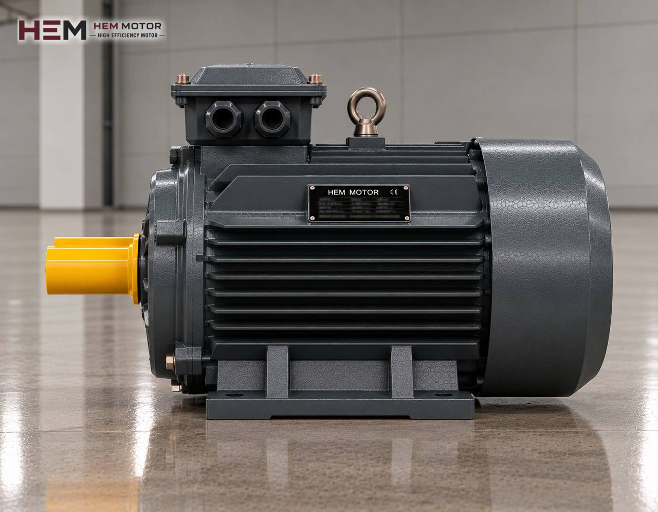
A chiller does not move chilled water by itself; the job of carrying water cooled in the evaporator to fan coils, air handling unit coils and process heat exchangers falls to one or more centrifugal pumps. This page explains how to select the three-phase motor that drives those pumps in industrial and commercial facilities such as hotels, hospitals, shopping centres, data centres and factories; for the wider picture of HVAC applications, see our HVAC sector electric motors page.

The Motor's Role and Its Limit in the Chilled Water Circuit
The motor's only job is to turn the pump impeller. The impeller adds pressure to the cold water leaving the evaporator; the water travels through the pipework to the consumers, returns after picking up heat and enters the evaporator again. What actually cools the water is the refrigeration cycle inside the chiller. The hermetic or semi-hermetic motor that drives the compressor runs inside the refrigerant and is a part supplied by the chiller manufacturer; it is outside the scope of this page and of standard motor selection.
To be clear: the motors discussed here are not spare parts for domestic split air conditioners or wall-mounted units. The subject is the industrial pump motor with an IEC frame that stands on its base in the plant room and is usually fed at 400 V.
Primary, Secondary and Process Pumps: Which Needs Which Motor?
The hydraulic layout of the plant is the first input to motor selection. In the classic primary-secondary arrangement, each chiller has a primary pump in front of it that passes a constant flow through the evaporator. Secondary pumps distribute water according to the building's changing demand and usually have their speed controlled. In newer plants a single variable primary flow pump group serves both the chiller and the building. In industry, a separate pump may also be assigned to process consumers such as moulds, extrusion lines or fermentation tanks.
The pump type also makes a difference. In inline pumps the motor stands vertically and is flanged to the pump casing; in end-suction pumps the motor sits horizontally on a foot-mounted base and transmits power to the impeller through a coupling. For large flows, split case pumps are preferred. For details see the inline pump motor and split case pump motor pages.
Deriving Motor Power and Speed from Pump Data
The right starting point is the pump manufacturer's performance curve. The design flow (m³/h) and head (m) are marked on the curve; the shaft power at that point is read, together with the highest shaft power that can be reached at the right end of the curve as flow increases. The motor is chosen with a rated power that also covers this second value. In chiller circuits this margin matters, because the operating point can shift when valves are throttled or a branch is taken out of service.
Speed comes with the impeller design. Four-pole motors, i.e. the approx. 1,500 rpm class, are common on chilled water pumps; compact pumps requiring higher head also use two-pole motors. Fitting a 2,900 rpm motor in place of one for a pump designed for 1,450 rpm raises both flow and power to an unacceptable degree. For an existing pump, the most reliable source is the old motor's nameplate; a kW figure on its own does not mean "the right power" for a chiller.
Connection Dimensions: Base, Flange and Shaft
The first item to compare is the IEC frame size, for example 160M or 180L. Even when the frame is the same, the following points are checked one by one:
- Mounting arrangement: foot-mounted (B3), flange-mounted (B5 or B14), foot-and-flange (B34, B35) or a vertical arrangement.
- Shaft diameter, shaft length and key size; on inline pumps the impeller often sits directly on the motor shaft, so this dimension is critical.
- Foot hole spacing and shaft centre height, against the existing holes in the base.
- Flange outside diameter, spigot diameter and bolt circle.
- Voltage, connection (star/delta) and rated current; compatibility with the existing panel and overload setting.
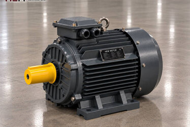
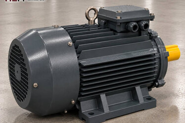
HEM Motor supplies its three-phase range in foot-mounted, flange-mounted, combined and vertical (V1, V3, V5, V6, V15) versions depending on frame; exact flange and shaft dimensions are confirmed during the order discussion. Frame dimensions are listed in the frame size table article.
Plant Room Conditions and Condensation on Cold Pipes
The surface of chilled water pipes and of the pump casing is often below the dew point of the surrounding air. On a poorly insulated pump the casing sweats, and droplets run onto the base and sometimes towards the motor's drive-end bearing. Our motors have IP55 protection; this protects against splashing water, but the motor is not designed to sit under constantly dripping condensate. Completing the pump insulation and turning the terminal box cable entry downwards are simple but effective measures.
Catalogue values apply to ambient temperatures between −15 and +40 degrees and altitudes up to 1,000 m. Pumps next to packaged chillers installed on roofs can exceed this limit in direct sun; if you have such a layout, a high-altitude site or seasonal shutdowns, state it in the order. An anti-condensation heater for moisture during long stops and a PTC or PT100 sensor for monitoring winding temperature can be added as order options.
Variable Flow, Inverters and Pump Staging
Secondary and variable primary pumps are usually driven by a frequency converter linked to a differential pressure sensor. Since pump load falls quickly with speed, the motor's own fan usually provides enough cooling at low speed; still, for an application that will run for long periods at very low speed with full torque, the need for a separate fan is assessed. If the panel is far from the motor, a dv/dt or sine filter comes into question. You can find the conditions for converter operation on the inverter-compatible motors page.
The chiller side has its own limit: if the flow through the evaporator drops below the minimum given by the chiller manufacturer, the flow switch stops the unit. The converter's minimum frequency is therefore set according to pump and chiller data. In multi-pump systems, staging pumps on and off in sequence and rotating the standby pump balances the motors' number of starts and running hours.
Selection Table: Example Motors by Circuit
| Pump duty | Typical operation | Motor-side attention | Example HEM model |
|---|---|---|---|
| Small process cooling circuit | Fixed speed, single pump | Flange size, sweating pipe | 5.5 kW 132S-4 (1,460 rpm, aluminium) |
| Primary pump in front of the chiller | Constant flow, runs with the chiller | Flow switch, base alignment | 18.5 kW 180M-4 (1,470 rpm, cast iron) |
| Building secondary pump | Inverter on differential pressure | Minimum frequency, cable length | 37 kW 225S-4 (1,485 rpm, cast iron) |
The models in the table are examples, not a final selection; the motor's suitability for the pump is verified separately with the pump curve, operating point, speed and connection dimensions.
What to Send Us When Replacing a Failed Pump Motor
The quickest route is a clear photo of the old motor's nameplate; how to take it is explained in the send motor nameplate guide. In addition to the nameplate you can share the following via WhatsApp; the numbers are on the contact page.
- Pump brand, type (inline, end-suction, split case) and the pump nameplate if possible
- Motor power, speed and voltage; star or delta connection
- Mounting type: foot, flange or vertical; flange and shaft size
- Whether the pump is in the primary, secondary or process circuit
- Whether it is driven by an inverter, and the cable length between panel and motor
- Installation location such as plant room, roof or open area
- Required quantity; state if a standby pump motor is included
Motor Groups to Explore in the Shop
All models are listed on the buy electric motors page. The cast iron frame motors category is a suitable starting point for large chilled water pumps, and the aluminium frame motors category for small process circuits. The models linked in the table above are examples; their suitability for the pump is verified separately. The circulation pump motor page is useful for general pump applications, and the cooling tower motor page if a tower is used on the chiller's condenser side.
Frequently Asked Questions
Can these motors also be used for the chiller's compressor motor?
No. Hermetic and semi-hermetic compressor motors are refrigerant-cooled parts specific to the chiller manufacturer and are not included in HEM Motor's 2026 catalogue. This page covers only the standard motor that turns the water pump.
Does the primary pump motor need to be driven by an inverter?
In the classic primary-secondary arrangement the primary pump mostly runs at fixed speed. In variable primary flow systems inverters are common; in that case the minimum speed is set according to the lowest evaporator flow the chiller allows.
The pump casing is sweating; does this affect the motor?
Dripping condensate can damage the bearing and terminal box in the long run. Complete the pump and pipe insulation; if the motor is in a position where it will stay wet, state this in the order.
The old motor is 1,450 rpm; can I fit a 2,900 rpm motor instead?
You should not. When the speed of a centrifugal pump doubles, the power drawn rises very sharply along with flow and pressure; both motor and pump are overloaded. The number of poles is chosen to match the pump's design speed.
How long can I keep a spare pump motor on the shelf?
It can be stored in a dry, vibration-free place, turning the shaft by hand from time to time. After long storage, having the insulation resistance measured before commissioning is good practice.