English
 Français
 Türkçe
 Español
 Русский

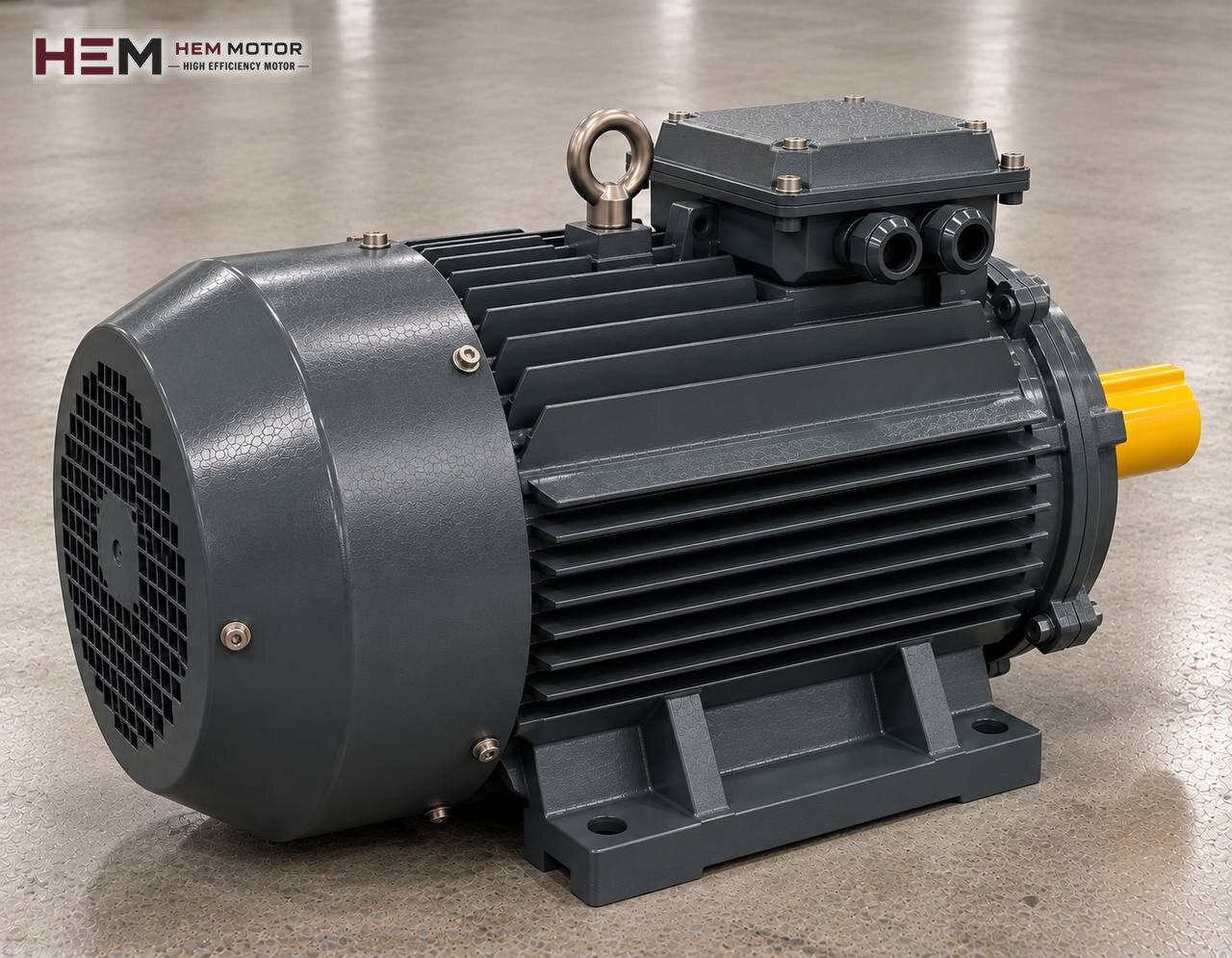
A feed grinding and milling machine reduces raw materials such as maize, barley, wheat and oilseed meal to a fineness suited to mixing and pelleting. The more evenly the grain is broken, the more homogeneous the mix, the firmer the pellet and the better the animal digests the feed. This page covers the motors that drive the hammer mill and the roller crusher in a feed plant, and what these machines specifically ask of the motor; for the other machines in the plant, have a look at the feed machinery electric motors page.

Two grinding methods in a feed plant
In the feed industry, grain is mostly broken by one of two machines. Which one is used changes the motor speed, the transmission and even the auxiliary motors in the plant.
Feed hammer mill
Free-swinging hammers on a rotor turning at high speed shatter the grain; the broken material leaves the mill once it passes through the perforated screen around the rotor. The screen hole size sets the product fineness: a coarser screen is fitted for poultry feed, a finer one for pig and fish feed. Because it accepts a wide range of materials, from grain to oilseed meal, it is the basic grinding machine of feed mills.
Roller feed crusher
Two or three pairs of grooved rollers turning towards each other crush and break the grain. It gives an even product with a low dust share and uses less energy than a hammer mill for the same job; on the other hand it is limited with fibrous material and very fine grinding. It is preferred for ruminant feed and for rolled barley or oats. Because the rollers turn at low speed, the motor is connected by belt or gearbox.
The motor on a hammer mill: high speed and direct coupling
In a feed mill, product fineness depends closely on the peripheral speed of the hammer tips. For this reason, in most large feed mills the rotor turns at the motor's own speed: 2-pole motors in the roughly 3000 rpm class are used, and on some large-diameter rotors 4-pole motors in the roughly 1500 rpm class. A flexible coupling sits between motor and rotor, and both rest on a common rigid base.
Direct coupling means that every imbalance in the rotor passes straight to the motor shaft and bearings. Checking coupling alignment with a dial gauge, keeping the base bolts tight and having a base of sufficient mass are the main factors that decide motor life on a high-speed mill. On a 2-pole motor, bearing and grease selection must also suit the speed; the lubrication interval is followed according to the value on the motor nameplate and in its catalogue.
Screen, feeding and motor current
The component that really sets the motor load on a feed mill is the feeder. The rotary drum or screw feeder on top of the mill spreads the grain evenly across the rotor. In modern plants the feeder speed is adjusted according to the mill motor current: when the current falls below the target, feeding increases; when it rises above, feeding decreases. The motor is thus kept at a stable load just below its nameplate current.
A blocked or torn screen upsets this balance. If damp grain or oily meal blinds the screen, material builds up around the rotor, the current rises and the product overheats. A torn screen lets coarse product through and the current drops unexpectedly. Watching the current curve gives the operator early information about the state of the screen. The feeder's own small motor is often driven by a frequency inverter.
Aspiration fan and reversible operation
Feed hammer mills usually work together with an aspiration system. The fan drawing air from under the mill speeds the passage of ground material through the screen, removes heat and moisture from the rotor chamber and stops dust from spreading. The fan motor is much smaller than the main motor, but if it stops, mill capacity falls and the main motor current rises. Interlocking the fan with the main motor is therefore useful.
On many feed mills the rotor can run in both directions, so both edges of the hammers are used. The direction is changed with a selector in the control panel by swapping two phases. The change should be made only after the rotor has stopped completely; a large rotor can take minutes to stop, and some machines have a brake to shorten this time.
Starting and supply conditions
The mill starts empty with the feed closed. However, the large-diameter rotor and coupling carry considerable inertia; the motor draws high current until it brings this mass up to rated speed. At high power, star-delta or a soft starter is used to avoid straining the supply; the reduced torque in star connection is usually enough for a mill starting empty, but the run-up takes longer. The starting time and rotor inertia should be obtained from the mill manufacturer and passed on to us when selecting the motor.
If the mill is stopped and started frequently during the day, successive starts heat the winding. Limiting the number of starts per hour and monitoring temperature with a PTC thermistor in the winding is good practice; a PTC/PT100 sensor is an order option. In a dusty mill room, keeping the motor frame and fan cover clean is essential for cooling. If a classified area with a dust explosion risk is involved, a standard IP55 motor is not designed for that condition; state this in the order.
Example HEM models and selection table
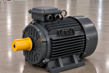
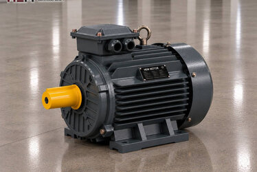
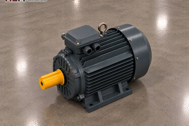
Direct-coupled feed hammer mills commonly use 2-pole cast iron motors. On a medium-capacity mill the 30 kW cast iron 200L1-2 delivers 96.8 Nm at 2,960 rpm. For larger mills, the 55 kW cast iron 250M-2 (2,970 rpm, 176.9 Nm) and the 90 kW cast iron 280M-2 (2,975 rpm, 288.9 Nm, service factor 1.15) are models worth checking. On a belt-driven roller crusher the 15 kW cast iron 160L-4 produces 97.8 Nm at 1,465 rpm.
| Machine | How the motor works | What to tell us | Example HEM model |
|---|---|---|---|
| Roller feed crusher | By belt, low roller speed | Pulley diameter, number of rollers | 160L-4, 15 kW |
| Medium hammer mill | By coupling, high speed | Base, coupling, direction of rotation | 200L1-2, 30 kW |
| Large hammer mill | Continuous load, fed by current | Starting method, PTC | 250M-2, 55 kW |
| High-capacity mill | High inertia, long run-up | Rotor inertia, starting time | 280M-2, 90 kW |
These pairings are for guidance; the right motor is determined by the rotor inertia and capacity of the mill, the required rotor speed, the connection method and the conditions in the mill room.
Information needed for a mill motor request
Tell us the type of machine (hammer or roller), its make and capacity, the rotor speed and the connection method (coupling or belt). Add the required power (kW) and speed (rpm), your supply voltage, the motor mounting type, the starting method, whether it runs in both directions, and the quantity. A nameplate photo of the existing motor lets us quickly confirm shaft and frame compatibility, especially on coupled mills.
You can see the large 2-pole frames in the cast iron series and current prices for all models on the shop page. Reach us by WhatsApp or phone using the numbers on the contact page.
Frequently Asked Questions
Can a 4-pole motor replace a 2-pole motor on a feed mill?
On a direct-coupled mill the rotor speed halves and the hammer tip speed drops; the product becomes coarser and capacity falls. The number of poles should be changed only if the mill manufacturer has designed the rotor diameter and screen for it.
Why does the mill motor current suddenly drop?
The feed may have been cut, the feeder may be blocked or the screen may be torn. If the screen is torn, coarse product passes through and the motor does less work; a drop in current is often the first sign of a fault.
Does a roller crusher need a separate motor for each roller?
On some machines a single motor turns two rollers at different speeds through gears or belts; on others each roller has its own motor. With separate motors, choosing both with the same power and speed is important for load sharing.
Can the mill motor be driven by an inverter?
Our three-phase motors are suitable for frequency inverter drive; at high power the inverter also limits the starting current. Changing the rotor speed affects product fineness, so the speed range should be set with the mill manufacturer; if the motor cable is long, the need for a filter is assessed with the order.