English
 Français
 Türkçe
 Español
 Русский

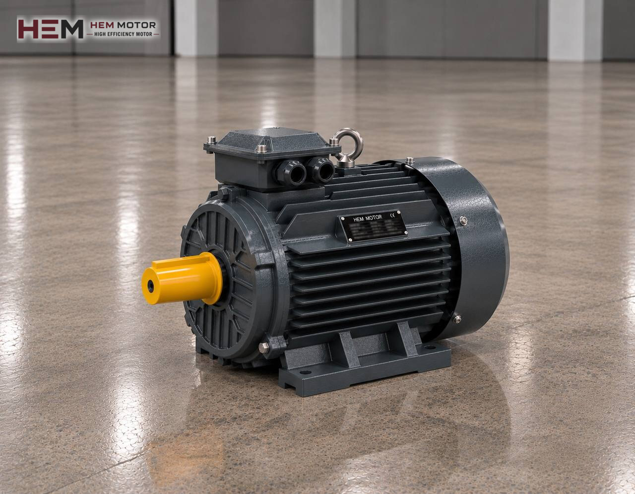
In mineral processing, cement, lime and industrial mineral plants, the machine that reduces coarse material from the crusher to flour fineness is usually a ball mill. From the motor's point of view, this machine means turning a heavy steel drum and the tonnes of balls inside it without interruption. This page covers the electric motor that turns the mill; for the plant's other drives, see the mining sector electric motor page.

How Mining and Cement Mills Differ
A ball mill works on the same principle in every industry: the grinding media inside the rotating drum rise, fall and break up the material. Operating conditions, however, differ. In ore preparation the mill usually runs wet; ore is fed as a slurry mixed with water and leaves through an overflow or grate discharge to the hydrocyclone. In cement and lime plants grinding is dry; the drum is divided into chambers, material is carried by an air stream and separated in a classifier.
This difference changes the motor's environment. Around a wet mill there is splashing slurry and moisture; around a dry mill there is fine, abrasive dust and hot grinding air. Laboratory and pilot plants have small drums, industrial plants large ones, and motor power varies across a very wide range accordingly.
The Load the Mill Places on the Motor
Lifting the charge
Most of the mill power is spent lifting the grinding media and material up one side of the drum. Because the charge lies piled on one side, the drum constantly turns against an unbalance torque. This torque changes as ball filling rises or balls are replenished; motor current is therefore a good indicator for monitoring the condition of the grinding media.
Starting with a frozen charge
In a wet mill that has stood for a long time, the slurry settles and hardens between the balls into a solid mass. At start-up this mass may rise with the drum as a single block and suddenly drop beyond a certain angle, which is dangerous for the liners, gearing and motor. Many plants loosen the charge before starting by slowly turning the drum with an auxiliary drive. The main motor's starting torque and acceleration time are determined from the mill manufacturer's data.
Drive Arrangements: Pinion, Gearbox, Coupling
Medium and large mills have a girth gear around the drum, turned by the pinion at the gearbox output. The motor is connected to the gearbox with a flexible coupling. On small mills the drum shaft turns through belts, pulleys and a gearbox, or through a direct geared drive. Because drum speed is low, six-pole or slower motors are often chosen to reduce the transmission ratio; in the HEM range this class has a synchronous speed of about 1,000 rpm.
The motor is usually placed on a concrete plinth or steel base with a foot-mounted B3 frame. Coupling alignment directly affects the life of a mill motor; alignment may shift as the drum heats up and the foundation settles, so periodic checks are needed. If a flange or foot-and-flange connection is required, a choice is made from the options offered for the frame, and shaft and flange dimensions are compared in the order. General information on gearboxes is on the electric motors for reducers page.
Starting and Variable Speed
As mills grow larger, starting current becomes a serious burden on the plant network. A soft starter limits current but also reduces torque; on a mill at risk of a frozen charge this must be assessed carefully. A frequency inverter, by contrast, provides a controlled start and also allows drum speed to be adjusted to ore hardness or the desired fineness.
HEM's three-phase motors can be run on an inverter. If the mill is to turn at full torque well below rated speed for long periods, the fan on the motor shaft may not be enough and a separate fan is considered; if the distance between panel and motor is long, a filter is assessed to protect the winding insulation. Sharing this information in the order is enough. Details are on the inverter compatible electric motors page.
Dust, Slurry and Heat: the Motor in the Mill Hall
In dry grinding, fine mineral dust settles on the motor's cooling fins and fan cover; over time it narrows the airflow and raises winding temperature. In wet grinding, slurry and wash water may splash. Our motors are IP55 protected; a direct water jet, pressure washing or immersion in slurry is outside this class, and in such cases a guard or special solution is needed and must be stated in the order.
A mill motor often runs for days without stopping. A PTC or PT100 sensor to monitor winding temperature and an anti-condensation heater against moisture during maintenance stops are order options. The bearing lubrication plan, coupling alignment, cleanliness of the fan cover and checking of the base bolts are part of regular maintenance. The cast iron frame series is used for this heavy, continuous duty.
Example HEM Models for Ball Mills
| Mill | Motor situation | What to check | Example HEM model |
|---|---|---|---|
| Pilot plant, wet grinding | Geared, continuous | Gearbox input, moisture | 15 kW, 978 rpm, 180L-6 cast iron |
| Lime or mineral mill | Dry grinding, dusty environment | Cleanliness of cooling fins | 75 kW, 985 rpm, 315S-6 cast iron |
| Ore mill, pinion driven | Heavy start, runs for days | Starting method, coupling alignment | 132 kW, 988 rpm, 315L2-6 cast iron |
| Large dry grinding line | On inverter, uninterrupted | Separate fan, winding sensor | 200 kW, 990 rpm, 355M2-6 cast iron |
These models are examples; the final selection is made with the mill manufacturer according to drum size, ball filling, required drum speed, transmission ratio and ambient conditions. Models of 75 kW and above have a service factor of 1.15; our range ends at 355 kW. Main drives above this limit are outside our range, but we can suggest models for auxiliary drives in the same plant such as feeders, pumps and classifiers.
Information for a Mill Motor Quotation
Send us the following: the machine (wet or dry mill, drive arrangement), power and speed of the existing motor, plant voltage, mounting type (foot, flange, on a plinth), starting method and quantity. If you attach a photo of the nameplate of the motor to be replaced, matching an equivalent becomes easier.
All models are listed on the buy electric motors page; the current price is on the product pages. For WhatsApp and phone contact, use our contact page.
Frequently Asked Questions
Why does mill motor current drop over time?
As the balls wear, the mass of the grinding media decreases and so does the power needed to turn the drum. A gradual fall in current often shows it is time to top up the balls; sudden changes may point to a feed, gear or bearing problem.
How does a frozen charge in a wet mill affect the motor?
A hardened charge can rise with the drum and drop suddenly, and the impact is transmitted to the gearing, liners and motor. Turning the drum slowly with an auxiliary drive before starting and delivering starting torque in a controlled way reduces this risk.
Why does the motor heat up on a dry grinding mill?
Fine dust fills the spaces between the cooling fins and clogs the fan cover; the motor runs hotter at the same load. Regular cleaning and, where possible, a position drawing clean air keep winding temperature within the nameplate limit.
Can a four-pole motor be used instead of a six-pole one?
It can, but the gearbox or pulley ratio must change to keep the drum speed. If the speed changes, the drum may approach critical speed and grinding suffers; this decision should be made with the mill manufacturer's approval.