English
 Türkçe

In mining and ore beneficiation plants, the flotation cell hosts one of the most demanding motor applications. The flotation agitator and aerator motor runs continuously, twenty-four hours a day and usually seven days a week, inside abrasive ore slurry. This motor must produce steady torque to keep solid particles suspended and at the same time provide the air entrainment required for froth flotation. A wrongly selected motor leads directly to overheating, premature bearing failure, loss of sealing and unplanned downtime that stops production. In this guide we walk through torque, protection class, duty type and material selection for flotation and ore beneficiation agitator motors, step by step and based on real mining conditions.
The Motor's Job in a Flotation Cell: Mixing, Suspension and Air Entrainment
Flotation is a beneficiation method in which finely ground ore is turned into a slurry with water, and air bubbles are entrained so that valuable minerals are carried to the surface as froth. At the heart of this process is the agitator motor that drives the rotor-stator assembly at the bottom of the cell. The motor has three core tasks: keeping the slurry homogeneous so solids do not settle, creating a suitable flow regime inside the cell, and breaking entrained air into fine bubbles that contact the mineral surfaces.
All three tasks force the motor to operate at the upper limit of continuity and torque. When the slurry stops, particles settle quickly, and on restart the motor is forced to turn within a heavy settled bed, which sharply increases the starting torque. Therefore a flotation motor must offer both high rated torque and a strong breakaway torque. To understand the torque-speed relationship better, our article on the asynchronous motor speed-torque curve and breakdown torque applies directly here.
Why Is Continuous (S1) Duty Essential?
Flotation lines are continuous processes. Dozens of cells in a flotation bank rotate at the same tempo at the same time. For this reason the agitator motor must be selected in S1 continuous duty, suitable for running at full load without interruption. A motor sized for intermittent duty heats up quickly and fatigues its insulation. To grasp duty types correctly, review our electric motor duty type (S1-S6) selection guide. Our IE3 and IE4 motors, with 100% copper windings and Class F insulation, are designed for this continuous duty profile.
Torque in Abrasive Slurry and Correct kW Selection
Ore slurry is an abrasive medium carrying hard silica and mineral particles. The rotor both moves the fluid and overcomes the resistance of these particles. The mixing load is directly related to the solids content (density) of the slurry, particle size, cell volume and rotor diameter. As the solids content rises, the slurry gets heavier and the required power increases.
When selecting motor power, base it on the shaft power figure given by the cell manufacturer and add a power margin (service factor) for continuous heavy duty. A motor sized too small approaches its breakdown torque in dense slurry and struggles; a motor sized too large suffers efficiency and power factor losses at part load. For correct sizing, our articles on at what load a motor should run and motor power calculation provide a practical starting point. For the contribution of service factor to overload capacity, see IE3 motor service factor and overload capacity.
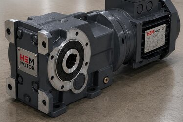
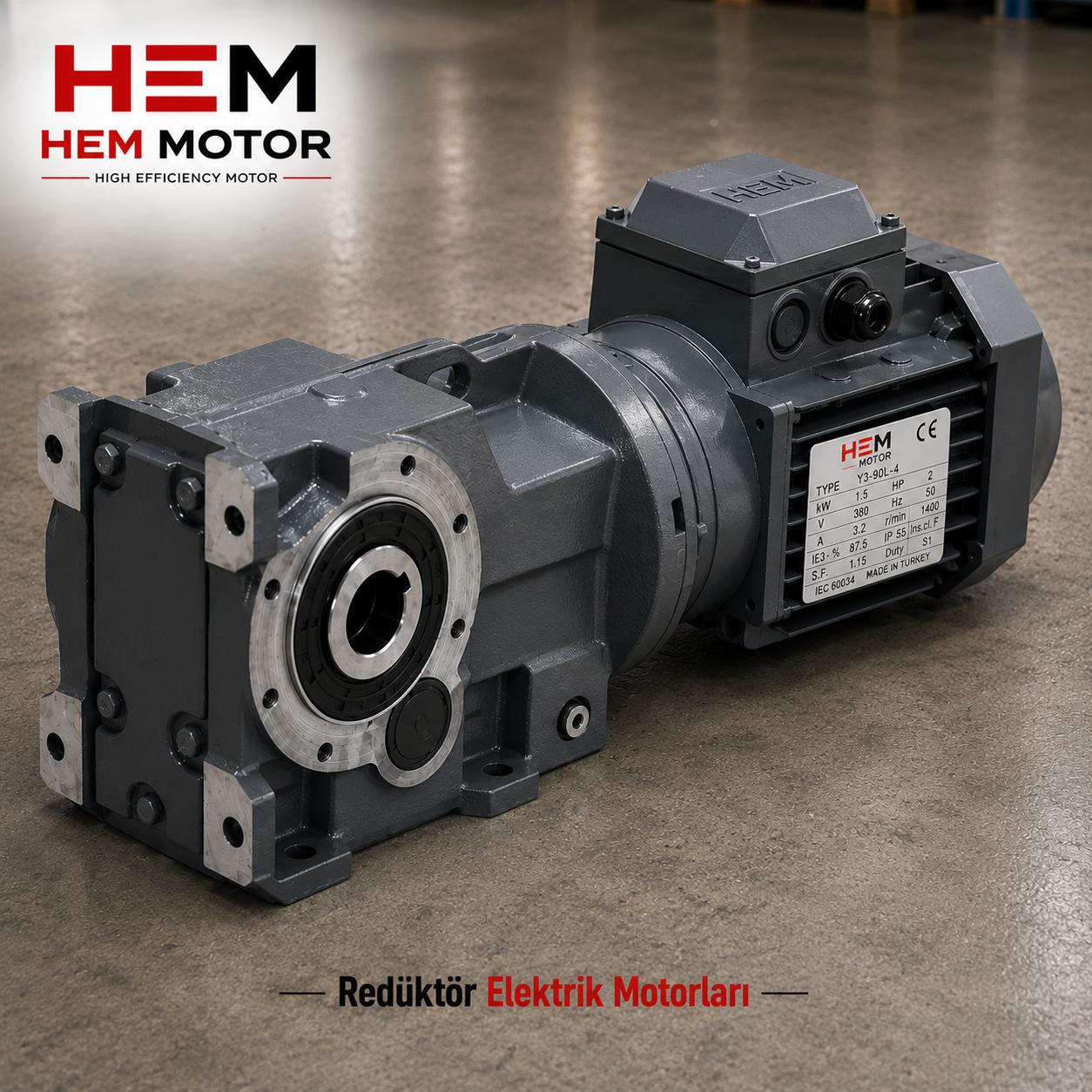
The Geared Low-Speed Solution
Flotation rotors usually turn at much lower speeds than the 1500 rpm motor speed. Therefore agitators are mostly driven through a gear reducer. The reducer both lowers the output speed and increases the output torque, so a smaller motor can be selected. The choice of bevel-helical or worm gear reducer is set by the required output speed and mounting arrangement. Geared motor versus separate motor plus reducer and monoblock geared motor purchasing are reference points for choosing the right package. For matching a motor to the reducer, our which electric motor fits a worm gear and NMRV reducer guide clarifies IEC frame and flange compatibility.
Protection Against Corrosion and Wear: IP65/IP66 and Cast Iron Body
The flotation environment is aggressive both chemically and physically. Around the cell there is constant water splash, acidic or alkaline reagent vapours, and a humid, dusty atmosphere. Under these conditions a standard IP55 motor may not last long; motors with higher protection against water and dust ingress, IP65 or IP66, should be preferred. To clarify the difference between protection classes, our electric motor IP protection class selection: IP55, IP65, IP66 article is the basic reference.
For the body material, cast iron is the natural choice for flotation in terms of mechanical strength and vibration damping. A cast iron frame carries heavy reducer loads and cell vibration without trouble. In a corrosive environment an additional cataphoresis coating and special paint layer markedly extend motor life. Cast iron motor paint and cataphoresis coating and corrosion protection of cast iron body motors explain which coating suits which environment. For the choice between cast iron and aluminium, see cast iron or aluminium body.
Sealing, Gaskets and Oil Seal
Agitator motors are mostly mounted vertically (V1) with the shaft pointing down. In this position the risk of water and slurry leaking into the motor is high, so the shaft-side oil seal and sealing come to the fore. For correct seal selection in vertical mounting, our vertical mounted electric motor selection (V1/V5) and cast iron motor oil seal and sealing articles are critical.
Froth, Air Entrainment and Aerator Motor Load
In some flotation cells the rotor also acts as an induction device drawing air into the cell; in others a separate aerator or blower is used. Air entrainment increases the load on the rotor and raises the current the motor draws. A stable froth layer depends on the right mixing speed; too high a speed breaks the froth, too low a speed lets particles settle. This balance requires the motor to hold its speed steady. Speed stability under sudden load changes matters; here the article on asynchronous motor torque design classes (N/H) and starting torque is useful. If a separate air blower is used, centrifugal and turbo blower motor selection covers blower sizing.
Starting and Protection Equipment
Large flotation agitators starting within settled slurry draw high starting current. To limit this current and reduce mechanical shock, soft starters or star-delta starting are preferred. The article starting AC asynchronous motors: star-delta or soft starter eases this decision. Protecting these continuously running motors against overload and phase loss is also vital; electric motor protection: thermal relay and fuse selection and single phasing (phase loss) in asynchronous motors complete the protection chain. Adding a PT100 or thermistor to monitor winding temperature is recommended on critical flotation motors; motor winding temperature monitoring: PT100 and PTC thermistor is detailed.
Dust, Moisture and Maintenance on the Mine Site
A flotation plant is usually located within the mine site, in a dusty and humid area. Integrate motor protection against site conditions with our stone quarry and mine site motor protection article. For pumps on the dewatering side of the abrasive slurry, mine dewatering and slurry pump motor selection; for the ore grinding side, mine and ore mill motors and ball and rod mill main drive motor cover the whole beneficiation line. To protect bearing life under shock and dust, crusher and mill motor bearing life clarifies greasing intervals.
Slurry Density, Particle Size and the Change in Motor Load
The load of a flotation motor is not constant; as the ore feed changes, the slurry density and particle size shift continuously. When the incoming ore hardens or the solids content rises, the mixing resistance increases and the motor draws more current. Therefore the motor should be selected so that it does not get too close to its breakdown torque even at the highest expected density. In practice, the motor is wanted to run a little below rated load most of the time, and near rated load under heavy feed. To assess the effect of this operating point on efficiency and power factor, the at what load a motor should run article is a guide. The drop in power factor and increase in reactive draw at part load directly affect the energy cost of continuously running flotation lines; therefore the capacitor selection advice in asynchronous motor power factor (cos fi) and correction reduces the plant's reactive penalty.
Since ore beneficiation plants are continuous and high-power, the choice of motor efficiency class makes a clear difference in the annual energy bill. An IE4 agitator motor instead of IE3 can pay back relatively quickly on a continuously running line. You can assess the efficiency class decision and payback in IE3 or IE4 electric motor investment and continuous-load savings in energy savings in pumps, fans and compressors with an IE5 motor.
Commissioning, Acceptance Inspection and Spare Motor Plan
When the flotation agitator motor arrives on site, insulation resistance (megger), rotation direction and vibration should be checked before commissioning. A motor that has waited in corrosive and humid storage may have absorbed moisture in its winding insulation; therefore acceptance inspection is a critical step. You can find these checks in the electric motor incoming and acceptance inspection and electric motor commissioning and first start-up checklist articles. If the motor will wait long in storage, the electric motor storage and long-term keeping article is important for moisture and bearing protection.
Since a flotation bank has dozens of identical motors, keeping spare motors at critical powers greatly reduces downtime risk. The failure of one cell motor can unbalance the whole bank; therefore a redundancy plan is more a necessity than a luxury for production continuity. You can plan the spare motor stock with the critical spare motor list for facilities article, and supply assurance in mining with the motor supply contracts in mining article. When replacing an existing motor with an equivalent, the avoid wrong motor delivery article helps with nameplate matching.
Frequently Asked Questions
Which IP protection class is suitable for a flotation agitator motor?
Because of water splash, reagent vapour and humid dust, at least IP65 and where possible IP66 is recommended for flotation agitators. Standard IP55 motors may be short-lived in this environment. See our IP protection class selection guide for details.
Why must a flotation motor be continuous (S1) duty?
Flotation lines are continuous processes; the motor turns at full load twenty-four hours a day. Therefore S1 continuous duty is essential. A motor sized for intermittent duty overheats and fatigues its insulation early.
Why is a reducer used on the agitator?
Flotation rotors turn at much lower speed than the motor. A reducer lowers the output speed and increases torque, allowing a smaller motor to be selected. Depending on the required output speed and mounting, a bevel-helical or worm gear reducer is chosen.
Get a Quote
For your flotation, aerator and ore beneficiation agitator motors we offer IE3 and IE4 motor solutions with IP65/IP66 protection suited to abrasive environments, cast iron bodies and continuous S1 duty. Share the cell manufacturer's nameplate data, output speed and solids content; let us determine the correct power, reducer and protection package together. For a fast quote reach us through our contact page or call +90 (532) 345 49 86. Browse our product range from our home page and from our crusher and stone crushing plant motor selection article.
Purchasing and Selection Checklist
1) Determine the shaft power and required output speed given by the cell manufacturer. 2) Clarify slurry solids content and particle size, then add a power margin. 3) Verify S1 continuous duty and a suitable service factor. 4) Request at least IP65, preferably IP66 protection class. 5) Ask for a cast iron body with cataphoresis/special paint against corrosion. 6) Confirm oil seal and sealing equipment in vertical (V1) mounting. 7) Choose reducer type and ratio according to output speed. 8) Decide the starting method (soft starter/star-delta) and thermal/phase protection. 9) Add temperature monitoring with PT100 or thermistor on critical motors. 10) Build a spare motor stock plan according to downtime cost.