 English
 Türkçe

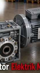
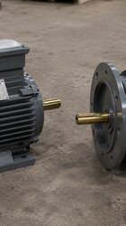
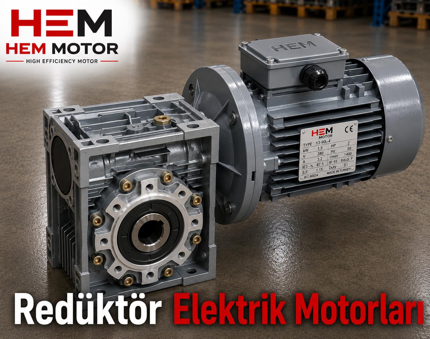

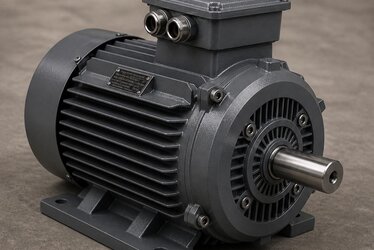
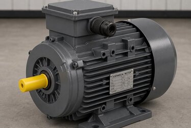
One of the most common assembly problems in the field is a mismatch that looks simple but has troublesome consequences: the electric motor not seating on the reducer. The cause is usually that the motor power does not match the reducer housing, or that the flange type (B5/B14) is wrong. A mismatched motor-reducer pair becomes useless at the moment of assembly even though it was ordered, shipped and brought to site. In this article we explain which electric motor fits worm gear and NMRV reducers, and how IEC frame and flange matching is done, kW by kW, flange by flange.
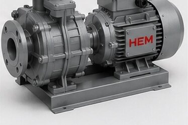
The advantage is this: when the motor and worm reducer are made on the same bench in mutually compatible dimensions, the matching problem disappears at the root. Because HEM makes both motors and worm reducers, the dimensions come out matching; the buyer does not have to guess whether the motor will seat on the reducer. Still, knowing the logic of correct matching strengthens every purchase decision.
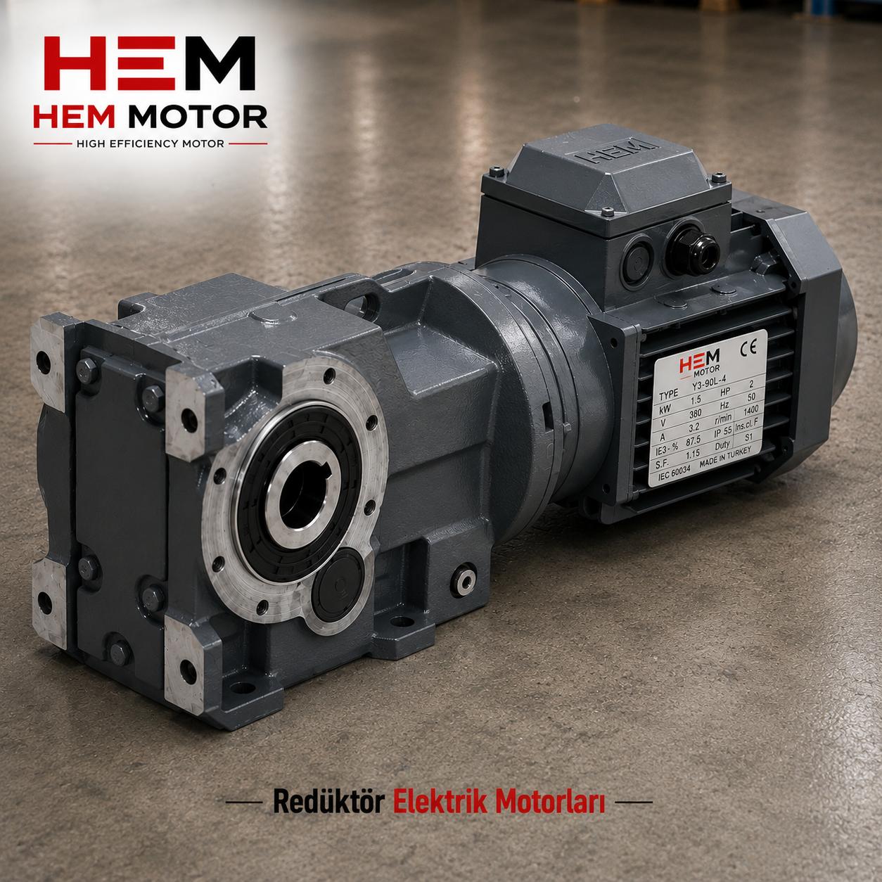
What Is a Worm Gear (NMRV) Reducer and Why Is It Common?
An NMRV reducer is a compact power transmission element working with a worm and helical gear pair, providing a high reduction ratio in a single stage. It is used in a wide field from conveyors to mixers, from door systems to packaging machines. The main reasons for its popularity are:
- High reduction: Provides a high ratio in a single stage; converts the high input speed into low speed and high torque at the output.
- Compact structure: Offers high torque in a small volume; suits tight mounting spaces.
- Various mounting: Provides flexibility in output shaft and mounting orientation.
- IEC input flange: Has an input flange to match standard IEC motors directly.
That last item is the heart of matching: the reducer's input side is designed for a specific IEC frame size and flange type. The motor must conform to these dimensions.
The Three Dimensions of Matching: Power, IEC Frame and Flange
Correct motor-reducer matching is achieved in three basic dimensions. If these three are not all correct at once, the motor either will not seat on the reducer or cannot perform its task.
1. Power (kW) Compatibility
Each reducer housing is designed to carry a specific power range. An oversized motor can exceed the reducer's carrying capacity and damage the gears; an undersized motor cannot do the required work. So the first step is to correctly determine the power the application requires. From HEM30 to HEM130 each housing matches a specific kW range; as the housing grows, the power and torque it can carry increase.
2. IEC Frame Size
The motor's IEC frame size (for example 71, 80, 90, 100/112, 132) must match the size the reducer's input flange will accept. The reducer's input side is bored for specific IEC frames; the motor's shaft diameter and flange holes must fit this size. A wrong IEC frame means the motor physically does not seat on the reducer.
3. Flange Type (B5/B14)
The third and most often skipped dimension is flange type. A B5 flange is a large-diameter connection face with through holes (through-bolted); a B14 flange is a smaller, threaded (face-bolted) connection. Whichever the reducer's input flange expects, the motor must be of that flange type. A B14 motor will not fit a reducer expecting B5, or vice versa.
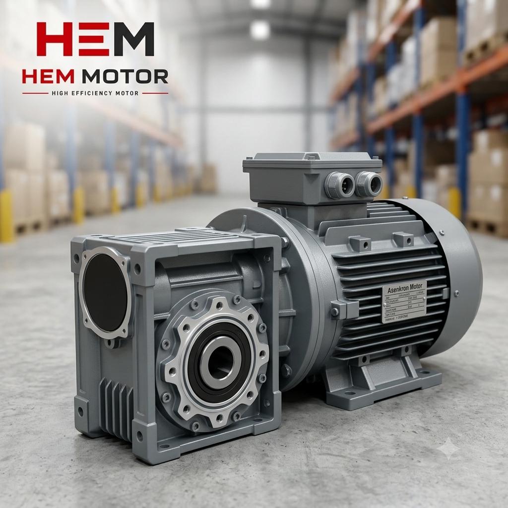
Frame-Power-Flange Matching from HEM30 to HEM130
Worm reducers are numbered by housing size, and each housing matches a specific power range, IEC input size and flange type. The general logic is:
- Small housings (HEM30-HEM50): For low-power applications; usually match small IEC frames (63, 71, 80) and B14 flange.
- Medium housings (HEM63-HEM90): Medium power range; 80, 90, 100/112 IEC frames with B5 or B14 flange options.
- Large housings (HEM110-HEM130): Applications demanding high torque; larger IEC frames and usually B5 flange.
This matching table clarifies, at the moment of purchase, the question of "which housing takes how many kW, which IEC size and which flange". When the right combination is chosen, the motor seats on the reducer smoothly and the system works on the first try. Our frame size and power matching guide, which covers correct frame and power matching more broadly, is a complementary resource.
Speed and Output Rate: Completing Motor Selection
Matching is not only physical seating; output speed also affects motor selection. The reducer's reduction ratio lowers the input speed at the output. To reach the desired output speed, the correct input speed (pole count) must be chosen.
- 4-pole motor (~1500 rpm): The most common input choice; standard in most NMRV applications.
- 2-pole motor (~3000 rpm): For special cases needing higher output speed.
- 6-pole motor (~1000 rpm): For lower output speed and smooth running.
For details of speed and pole selection you can consult our pole selection guide. The right pole guarantees the right output speed and torque.
Mounting Position and Output Shaft Orientation
In worm reducers not only the input side but also the output side is chosen according to the application. The output shaft can be a solid shaft or a hollow (bored) shaft; the mounting position can be horizontal or vertical. These choices affect how the motor is positioned and therefore the input flange orientation. Correct matching requires thinking of this whole together.
- Solid shaft output: The standard solution for applications to be connected by a coupling.
- Hollow (bored) shaft output: Slides directly onto the drive shaft to save space; common in mixers and conveyors.
- Mounting foot or flange: The way the reducer fixes to the structure can be foot-mounted or output-flanged.
- Lubrication orientation: The mounting position affects the reducer's oil level and lubrication performance, so the position should be stated in advance.
These details determine how and in which orientation the motor physically connects to the reducer. Describing the application correctly from the start guarantees the right choice on both the motor and reducer side.
Common Matching Mistakes
Some recurring mistakes in motor-reducer matching cause loss of time and money in the field. Knowing them in advance makes it easier to build a pre-order checklist.
- Looking only at power: Even if the correct kW is chosen, a wrong IEC frame or flange causes the motor not to seat.
- Skipping flange type: Confusion between B5 and B14 is the most common mistake; it must be clarified before ordering.
- Ignoring shaft diameter: Even if the IEC frame is correct, special shaft diameter requests must be checked.
- Not calculating output speed: The wrong pole count means the wrong output speed despite correct physical matching.
The safest way to avoid these mistakes is to supply the motor and reducer from a single source that makes them compatibly, describing the application completely.
Why Is Buying the Match from a Single Supplier Advantageous?
Supplying the motor and reducer separately from different sources puts the matching responsibility on the buyer. But when the motor and worm reducer are made by the same producer in compatible dimensions, the buyer only describes the application; the rest is guaranteed by the supplier. This approach eliminates surprises at assembly and shortens delivery time.
A compatible motor-reducer package means both ease of assembly and long life. You can reach our wide product range from our homepage and clarify the combination suited to your application.
FAQ
Which motor flange fits an NMRV reducer: B5 or B14?
This depends on the design of the reducer's input flange. A B5 flange is a large-diameter, through-bolted connection; a B14 flange is a smaller, threaded (face-bolted) connection. Whichever the reducer's input side expects, the motor must be of that flange type. Small-housing reducers usually want B14, larger housings want B5. Clarifying the flange type before ordering prevents the assembly problem.
Why must motor power match the reducer housing?
Because each reducer housing is designed for a specific power and torque range. An oversized motor can overstrain the reducer's gears and cause early failure; an undersized motor cannot drive the application. Correct matching is achieved by choosing a motor that gives the power the application requires while staying within the kW range the housing can carry.
What is the advantage of buying the motor and reducer from the same supplier?
When the motor and worm reducer are made on the same bench in compatible dimensions, IEC frame and flange matching is guaranteed. The buyer does not have to guess whether the motor will seat on the reducer; they only describe the application. This eliminates surprises at assembly, reduces the risk of wrong delivery to zero, and shortens commissioning time.