English
 Türkçe
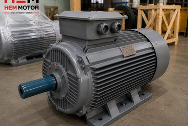
When buying an asynchronous motor, most businesses carefully study the power (kW) and efficiency class (IE3/IE4) but overlook the "cos phi" value on the nameplate. Yet the power factor directly affects the reactive penalty line on your electricity bill, how much your transformer is loaded and your cable cross-section. Especially when a motor runs below its rated load, that is at part load, the power factor falls quickly and unnecessary reactive power is drawn from the grid. In this guide we cover the cos phi concept, why it drops at part load, the cost of reactive power, the selection of an individual (at-motor) compensation capacitor, the power factor in IE3/IE4 motors and the effect of the variable frequency drive (VFD) on this picture.
What Is Power Factor (cos phi)?
An asynchronous motor draws reactive power to build its magnetic field, alongside the active power doing work at the shaft. The total apparent power drawn from the grid (kVA) is the resultant of active power (kW) and reactive power (kVAr). The power factor (cos phi or cos φ) is the ratio of active power to apparent power:
- Active power (kW): the power that actually does work and turns the shaft.
- Reactive power (kVAr): the power that oscillates to create the magnetic field and does no useful work.
- Apparent power (kVA): the total power the grid, cable and transformer must carry.
The closer cos phi is to 1, the "cleaner" the current the motor draws. In a typical 4-pole asynchronous motor cos phi is between 0.80 and 0.88 at full load. As the power factor drops, more current is drawn from the grid to do the same work, which increases losses and cost. We explained the basic operating principle in asynchronous motor slip and actual speed and the nameplate values in reading the IE3 motor nameplate.
Why Does cos phi Drop at Part Load?
The reactive power an asynchronous motor draws does not change much with load, because the magnetic field must be built even when the motor turns almost unloaded. Active power, however, decreases with load. As a result, when the motor runs below rated load, the share of the constant reactive power grows in the total and cos phi falls. In practice:
- A motor with cos phi 0.85 at full load can drop to around 0.70 at half load and around 0.50 at quarter load.
- A motor running unloaded draws almost entirely reactive power; cos phi falls sharply.
This is why selecting a motor larger than needed (oversizing) lowers both efficiency and power factor. We covered the importance of correct sizing in detail in what load to run a motor at and motor power calculation. Selecting the motor for the actual need lowers both reactive draw and energy cost.
Reactive Power and Grid Penalty
Electricity distribution companies meter the reactive power drawn and penalise consumption above a certain ratio. Businesses usually must not exceed a defined reactive limit relative to active energy; when exceeded a reactive penalty charge is added to the bill. A motor park running at a low power factor:
- Unnecessarily loads the transformer and main panel; the existing transformer fills up for less real work.
- Creates extra heating and losses in cables and switchgear.
- Increases voltage drop and affects the performance of motors at the end of the line.
Therefore correcting reactive power at source, that is bringing the power factor close to 1, means direct savings for the business. We covered the high-efficiency motor side of this topic in power factor and reactive penalty in high-efficiency motors. For audit preparation see our energy efficiency audit and motor inventory article.
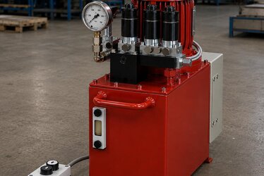
Compensation: Correcting the Power Factor
The way to correct the power factor is to balance the inductive reactive power the motor draws with capacitors that produce capacitive reactive power. This is called compensation. There are two basic approaches:
- Central compensation: a capacitor bank and a reactive power relay are used at the main panel; the reactive power of the whole plant is corrected collectively.
- Individual (at-motor) compensation: the capacitor is connected directly to the motor terminals; it engages when the motor runs and disengages when it stops.
On large motors running continuously, at-motor compensation is advantageous because it relieves the cables and panel of reactive load. To wire the terminals correctly, our motor terminal connection and voltage selection article guides you.
Care in At-Motor Capacitor Selection
If the at-motor compensation capacitor is selected too large in kVAr, the motor can self-excite while still coasting after it stops, producing dangerous overvoltage. Therefore the at-motor capacitor is sized according to the motor magnetising current, generally to stay below the reactive power the motor draws when unloaded. In applications where the capacitor is connected directly to the motor terminals no separate switching is needed; it engages with the motor. On motors using star-delta starting, the capacitor connection point must be planned separately; we explained this in star-delta and softstarter.
Power Factor in IE3 and IE4 Motors
A high efficiency class does not always mean a high power factor; these are different concepts. Efficiency shows the smallness of losses; power factor shows the share of reactive power. That said, modern IE3 and IE4 motors generally also offer a good power factor thanks to their optimised magnetic designs. In IE4 Super Premium motors both efficiency and power factor are kept balanced, which lowers both the active and reactive energy costs of the business. We covered the relationship between efficiency and power factor in IE4 motor efficiency losses and real field efficiency in nameplate vs field efficiency difference. For the IE3 vs IE4 investment decision see IE3 or IE4.
Power Factor in Motors Running on a VFD
If a motor is fed through a variable frequency drive, the power factor picture changes. The power factor on the input side of the drive is independent of the motor power factor on the output side. The input stage of modern VFDs generally provides a high power factor; in this case a compensation capacitor is not connected to the motor terminals, because the capacitor can be damaged by the drive output waveform. We explained running an asynchronous motor with a VFD in variable frequency drive (VFD) with an asynchronous motor and the savings it provides in pumps and fans in high-efficiency motor plus variable frequency drive. Key rule: never connect a capacitor directly to the terminals of a VFD-fed motor.
Reducing Reactive Draw with Correct Motor Selection
The ways to reduce the power factor problem at source are:
- Correct sizing: selecting the motor to run in the 75-100% band of rated load; avoiding oversizing.
- Choosing the pole count for the need: unnecessarily high speed can create unnecessary power and a low load ratio; our 2, 4, 6 pole selection article guides you.
- Using a modern, quality-wound motor: 100% copper winding and good magnetic design improve both efficiency and power factor.
- Using a VFD in variable-load applications: managing reactive draw by reducing speed on loads like pumps and fans.
To evaluate all these decisions together, our electric motor purchasing map and our total cost of ownership (TCO) article explaining the TCO approach are a good start.
Power Factor, Efficiency and Load Ratio: Reading the Three Together
The electrical behaviour of a motor must be understood not by a single number but by interpreting three values together: efficiency, power factor and load ratio. Efficiency shows how much of the power drawn is transferred to the shaft; power factor shows how much of the current drawn does work; load ratio shows at what percentage of rated power the motor runs. These three affect each other. For example when a motor is oversized, it both moves away from the peak of its efficiency curve and has a lower power factor; so loss is experienced on two fronts at once.
The ideal operating zone for most asynchronous motors is the band between about three quarters of rated power and full load. In this band both efficiency and power factor stay close to their peak values. Placing the motor in this band starts with correct power selection at purchase. A motor chosen too large, even if bought on a "just in case" logic, creates a hidden cost by running for years at both low efficiency and low power factor. We covered the correct load ratio and sizing in detail in what load to run a motor at and the effect of pole selection in efficiency and pole count in asynchronous motors. We showed how to read efficiency and power factor from the nameplate in reading the IE3 motor nameplate.
The Cost of a Low Power Factor to Cables and Transformer
When the power factor drops, the total current drawn from the grid (the apparent current) increases to do the same active work. This increased current affects the entire electrical infrastructure of the plant. Since heat loss in cables (joule loss) is proportional to the square of the current, a low power factor visibly enlarges cable losses. The same cable heats up more for the same real work; this means both energy loss and shortened cable life. In some cases the business is forced to increase the existing cable cross-section or run a new line because of the low power factor.
The situation is similar on the transformer side. A transformer capacity is defined in kVA (apparent power). A plant with a low power factor fills the kVA capacity of the transformer much faster than the real work requires. So a 1000 kVA transformer can fill up for far less real kW work because of a low power factor; when the plant wants to grow, the transformer capacity falls short and an expensive transformer upgrade comes onto the agenda. Correcting the power factor with compensation removes these hidden costs, relieving the existing infrastructure and opening growth capacity. In generator-powered plants, a low power factor leads to the generator being selected larger than necessary; we covered this in how many kVA generator handles how many kW motor.
Maintenance and Life of the Compensation Capacitor
Compensation capacitors, just like motors, have a certain life and lose their function when neglected. Capacitors lose capacitance over time; over the years the reactive power they produce decreases and the plant power factor begins to fall again without notice. So the reactive penalty can reappear on the bill even though a capacitor is connected. A regular check is the only way to be sure the capacitor capacitance is preserved.
The biggest enemies of capacitors are excessive temperature and harmonic distortion. Capacitors operating in a hot panel age faster; good ventilation extends their life. If there are many frequency drives in the plant, the resulting harmonics can overload the capacitors and lead to faults up to and including explosion. In such plants compensation panels with harmonic filters (reactors) are preferred. Correct motor selection, quality winding and a current efficiency class reduce both reactive draw and harmonic generation from the start, easing the load on the compensation system. We covered the contribution of an efficient motor park to energy management in ISO 50001 energy management and motor efficiency and the measurement of annual saving in measuring and documenting annual energy savings.
Frequently Asked Questions
How is an at-motor capacitor sized?
The at-motor compensation capacitor is sized to stay below the reactive power the motor draws when unloaded. If selected too large, the motor can self-excite while coasting after it stops and produce dangerous overvoltage. When the motor power, pole count and magnetising current are known, the correct kVAr value can be determined. We can calculate the right value for you using the information on your motor nameplate.
Can I fit a capacitor to a motor running on a VFD?
No. A compensation capacitor is not connected to the output of the frequency drive, that is to the motor terminals; the drive output waveform can damage the capacitor and cause a fault. The input power factor of a VFD is already generally high. If needed, correction is done with dedicated solutions on the input side of the drive.
Is a low cos phi only a billing issue?
No. Besides the reactive penalty on the bill, a low power factor leads to unnecessary loading of the transformer and cables, extra heating, voltage drop and early saturation of existing infrastructure. So in a plant that wants to grow, a low power factor also narrows new investment capacity. That is why compensation matters for both cost and capacity.
Get a Quote
Let us evaluate your motor park power factor, load profile and reactive draw and plan together the right motor selection and, if needed, an at-motor compensation solution. For our high power factor, 100% copper winding IE3 and IE4 motors, reach us via our contact page or request a quote on +90 (532) 345 49 86. You can find our product range on our efficient electric motors and worm gear reducers pages, and all our guides on our blog home page.
Purchasing and Selection Checklist
- Check the cos phi value on the nameplate; prefer 0.80 and above at full load.
- Size the motor correctly; target the 75-100% load band and avoid oversizing.
- Consider at-motor compensation on large continuously running motors.
- Select the capacitor below the motor unloaded reactive power; beware of self-excitation risk.
- Do not connect a capacitor to the terminals of a VFD-fed motor.
- Evaluate efficiency and power factor separately; both affect cost.
- Review your reactive penalty limit and the loading of your existing transformer.
- Carry out a plant-wide energy audit and motor inventory.