English
 Türkçe
IE5 synchronous reluctance (SynRM) motors stand out not only for their ultra-premium efficiency class but also for the dynamic torque behaviour they gain through drive control. In applications carrying pulsating (impulse) loads — presses, mills, crusher feeders, rolling stands — the real question is not just “how efficient” but “how far does speed dip on a sudden load step, and how fast does the motor recover torque?” In this article we examine the IE5 SynRM motor’s torque response to sudden load changes, its speed stability (recovery) and correct drive selection from an engineering perspective. We begin by recalling why SynRM cannot run without a drive.
SynRM and the Drive: The Basis of Torque Production
A synchronous reluctance motor carries neither magnets nor windings on its rotor; torque is produced through the rotor’s reluctance (magnetic resistance) difference — the Ld/Lq ratio between the d and q axes. This makes the motor light, cool and magnet-free, but it cannot start directly across the line on its own. It must always run under vector control via a variable frequency drive (VFD). To go deeper, see why IE5 synchronous reluctance motors cannot run without a drive and the technology overview in IE5 and synchronous reluctance motors.
The quality of the sudden-load response depends largely on the drive’s control architecture. Because SynRM operates with a different power factor and magnetic character than an induction motor, it is critical that the drive correctly identifies the motor model (autotune). The comparison in IE4 asynchronous vs synchronous reluctance makes this difference concrete, while the current and power-factor side is covered in IE5 SynRM rated current and power factor.
What Happens on a Sudden Load Step? Speed Dip and Recovery
The instant a press tool meets the material, or a large lump enters a mill, the load torque on the shaft multiplies within milliseconds. The motor’s reaction to this “load step” is examined in three phases:
1. Speed Dip
When load rises abruptly, speed drops slightly until the motor torque catches up with the new load. The depth of this dip depends on the drive’s speed-loop tuning (gains), the combined motor + load inertia (J) and the drive’s response bandwidth. Thanks to its high torque density, a well-tuned SynRM shows a shallow dip.
2. Torque Response
Under closed-loop vector control the drive rapidly raises the torque-producing current component. In modern drives the torque rise time is in the order of a few milliseconds, enabling SynRM to recover quickly under pulsating loads.
3. Speed Recovery
Once torque balances the new load, speed climbs back to the setpoint. In a well-parameterised system the recovery is sub-second and without overshoot. The article on impulse loads, impact-load motor selection: flywheel, inertia and crusher drive, shows how inertia management improves all three phases.
Closed-Loop or Sensorless Vector?
SynRM drives operate in two basic control modes:
- Sensorless (encoderless) vector control: estimates speed from the motor model. Sufficient and cost-effective for pumps, fans and general conveyors with soft load steps, but accuracy falls at very low speed and under harsh load steps.
- Closed-loop (encoder) vector control: an encoder on the shaft measures actual speed. For hard pulsating loads — presses, mills, rolling mills — and where full torque is needed at zero speed, it maximises speed stability and torque accuracy.
The hardness of the load determines which mode is required. For commissioning and parameters, see IE5 SynRM drive parameterisation. When a VFD is needed in general is summarised in VFD with an asynchronous motor.
Torque Limit and Overload Management
To protect the motor and mechanics, the drive operates with a torque limit. Setting this correctly under pulsating load matters in two ways: set too low, the motor cannot carry the load and speed collapses; set too high, the belt, coupling and gearbox are overstressed. SynRM’s short-time overload capacity must be evaluated together with the drive’s current reserve. Thermals matter: frequent, harsh load steps heat the motor. Its thermal behaviour under drive operation is covered in IE5 SynRM thermal behaviour and cooling, and forced cooling at low speed in IE4 motor external forced cooling fan.
Inertia (J), Flywheel and Speed Stability
The strongest mechanical factor governing speed stability under pulsating load is system inertia. High inertia physically softens the speed dip on a sudden load step — which is why flywheels are used on crusher and mill drives. However, high inertia increases start-up time and the drive’s acceleration load. The right balance is reached by computing motor + load + flywheel inertia together. For soft starting at high inertia, see crusher motor starting and, at high power, liquid resistance starter.
SynRM’s Part-Load Advantage
Pulsating loads often have a low average load plus a peak-impulse profile. SynRM’s greatest strength is preserving efficiency at part and low load better than induction motors — meaning energy savings during the low-load periods between impulses. See IE5 SynRM efficiency curve: why it excels at part load and IE4 motor part and low-load efficiency. These also show how oversizing eats into savings.
Choosing the Right Drive: What to Check
When selecting a drive for an IE5 SynRM under pulsating load, the key criteria are:
- SynRM support: the drive must support a synchronous reluctance motor profile and autotune. Standard induction parameters will not deliver full SynRM performance.
- Control mode: encoder input (closed loop) support is sought for hard pulsating loads.
- Overload reserve: short-time current capacity (e.g. 150-200%) to meet the peak impulse.
- Speed-loop bandwidth: enough control speed for fast torque response and shallow dip.
- DC bus and supply compatibility: for the correct input voltage and panel selection, see IE5 SynRM drive DC bus voltage.
For motor-drive sizing and frame matching, see IE5 SynRM frame-power table, and for installation compatibility drive and installation compatibility on IE5 transition. For a wider range, see our electric motors category and our home page.
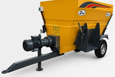
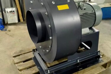
Pulsating Load Application Examples
Press benches, hammer mills, crusher feeders, rolling stands are typical pulsating-load examples. For the right drive in these, see hammer mill motor selection, twin-shaft shredder motor selection and the speed-torque (M-n) curve and breakdown torque, which help you match the motor to your load profile.
Speed-Loop Tuning: The Real Factor Behind the Dip
How far the speed dips on a sudden load step, and how fast it recovers, depends largely on the proportional (P) and integral (I) gain settings in the drive’s speed loop. High gain gives a fast, firm response and reduces the dip, but if raised too far the system oscillates and stresses the mechanics. Low gain gives a soft but slow response; the speed dips deeper and recovery lags. The right setting is found experimentally during commissioning according to the load’s inertia and hardness. In modern drives, automatic gain tuning (autotune) provides a starting point, but fine tuning under pulsating load is usually done manually. This tuning logic also applies to driving induction motors with a VFD; for comparison, see VFD with an asynchronous motor. In regimes such as frequent start-stop and jogging, heating must also be considered; see jogging and frequent start-stop (inching) and starts-per-hour limit.
SynRM’s Dynamic Advantage over Induction
An induction motor produces torque through current induced in the rotor, which introduces a small magnetic lag (rotor time constant) on a load step. In a synchronous reluctance motor, torque is directly tied to rotor position and magnetic geometry; the drive steers the current within milliseconds to build torque rapidly. The practical result is that a correctly parameterised SynRM holds speed more stably under harsh load steps than an induction motor of the same power. But this advantage is tightly bound to the drive: because SynRM exhibits a different power factor and magnetic character than induction at rated current, panel, cable and protection selection are made accordingly. The topic is detailed in SynRM rated current and power factor, and its difference from magnet motors in SynRM vs PM motor difference. The efficiency-cost balance is covered in IE5 or IE4.
Commissioning: Verifying Torque Response in the Field
The real performance of an IE5 SynRM + drive package under pulsating load must not remain on paper but be verified in the field during commissioning. Typical steps: teaching the motor model via autotune, tuning the speed-loop gains to the load, setting the torque limit to protect the mechanics, and observing the speed dip and recovery time during a real load impulse. This verification heads off future speed-instability or overstress problems from the start. The commissioning checklist is covered in drive and installation compatibility on IE5 transition and general first start-up in motor commissioning and first start-up. For the retrofit scenario of replacing an old motor with a drive-fed IE5, see IE5 + drive retrofit. For a total-cost-of-ownership comparison, see IE5, IE4 and IE3 TCO comparison.
Frequently Asked Questions
Is an IE5 SynRM more stable than an induction motor on a sudden load step?
With the right drive and tuning, yes. Thanks to high torque density and fast vector control, SynRM can keep the speed dip shallow and recover quickly. This advantage, however, depends largely on selecting the right drive and using closed-loop mode where required.
Is sensorless vector enough under pulsating load, or is an encoder required?
For applications with soft load steps, sensorless vector is usually sufficient. For presses, rolling mills and heavy pulsating mills where full torque is needed at very low speed, encoder-based closed-loop control is recommended for speed stability and torque accuracy.
How should I set the torque limit?
The torque limit should be high enough to meet the peak impulse yet low enough to protect the belt, coupling and gearbox. It is set by considering the mechanical drivetrain’s strength together with the motor’s short-time overload capacity, and is best confirmed by measurement during commissioning.
Get a Quote
Let us size the IE5 synchronous reluctance motor and a suitable drive package together for your pulsating-load facility. Share your load profile, speed and power needs, and we will recommend the motor-drive combination that delivers the right torque response. For a fast quote, call +90 (532) 345 49 86 or write to us via our contact page.
Purchasing and Selection Checklist
- Has the load profile been defined? (Continuous or pulsating; peak/average ratio)
- Have the required torque and speed range been calculated?
- Has the control mode been selected? (Sensorless vector / encoder closed loop)
- Does the drive support a SynRM profile and autotune?
- Is there enough current/torque reserve for overload (peak impulse)?
- Have system inertia and, if needed, a flywheel been evaluated?
- Have thermal behaviour and low-speed cooling been planned?
- Have DC bus voltage, supply and panel compatibility been checked?
- Is an autotune and speed-loop tuning plan ready for commissioning?