English
 Türkçe
When ordering an electric motor there is one parameter as critical as power, speed and efficiency class, and it often comes to mind last: the mounting type. The mounting code (IM code) that determines how the motor connects to the machine, whether it is held by feet or by a flange, and whether it runs horizontally or vertically, will simply not fit the field if chosen wrongly, even if the motor is perfect on paper. A foot-mounted motor cannot be bolted to a flanged pump; a small-flange motor cannot fit a large-flange gearbox. In this comprehensive guide we cover the IM mounting codes from start to finish: B3 (foot), B5 (large flange FF), B14 (small flange FT), B35 (foot + flange), V1/V3/V5/V6 (vertical positions) and the IM B / IM V code logic. You will find together which mounting is used in which application, what the flange dimensions express, and a checklist for error-free ordering. You can use this article like a glossary and reference.
What Is the IM Code and How Is It Read?
IM is the abbreviation of "International Mounting" and is defined according to the IEC 60034-7 standard. It expresses the mounting position of a motor in two different notations: a short code (e.g. IM B3, IM B5, IM V1) and a numeric code (e.g. IM 1001, IM 3001, IM 3011). In practice the short codes are the most widely used. The letters and digits of the code tell how the motor is fixed and which way the shaft end faces.
The code logic is simple: codes starting with "B" generally express horizontal-shaft (shaft horizontal) mountings, and codes starting with "V" express vertical-shaft (shaft down or up) mountings. The digit that follows determines the fixing method and shaft direction. For example, B3 defines a horizontal motor fixed by feet, B5 a horizontal motor fixed by a large flange, and V1 a vertical motor with the flange on top and the shaft facing down. To grasp the basic logic of these codes, our motor IM mounting code reading guide is a fundamental starting point.
Horizontal Mounting Types: B3, B5, B14, B35
Horizontal mounting is the most common group of motors running with the shaft parallel to the ground. There are four basic types, and each offers a different connection method.
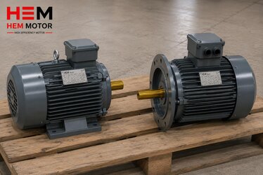
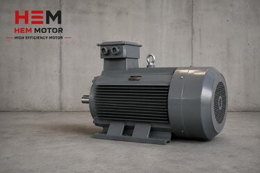
- B3 (foot): The classic type where the motor is bolted to the floor or a base through the feet under the frame. The large majority of belt-pulley drives, directly coupled groups and general industrial applications are B3. It is the most economical and most common mounting type.
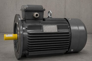
- B5 (large flange, FF): On the front cover, around the shaft end, there is a large-diameter flange with holes passing outside the flange (clearance holes). This flange bolts directly to a pump, gearbox or machine. There are no feet; the motor is carried entirely by the flange. The FF designation indicates the hole type of the flange.
- B14 (small flange, FT): Similar to B5 but the flange is smaller in diameter and its holes are tapped, that is, screwed from inside the flange. It is generally used in small-power motors, compact pump and gearbox connections. The FT designation expresses the tapped flange.
- B35 (foot + flange): Both feet and a large flange (B3 + B5) are present together. The motor both sits on the floor by its feet and connects to the machine by the flange. This dual support provides extra rigidity in heavy or vibrating applications and eases alignment.
The choice among these four types depends on the interface of the machine the motor will connect to. If the pump or gearbox expects a flanged connection, B5 or B14 is preferred; if the machine offers a footed base, B3 is preferred. For plants that want to make both foot and flange substitution with a single stock code, multi-mount (universal frame) solutions exist; the multi-mount (B3/B5/B35) universal frame in IE3 motors article explains foot and flange substitution from a single code.
What Do Flange Dimensions Express?
In flanged motors (B5/B14), knowing the flange dimensions is essential for correct ordering. The flange is defined by a letter-number code (for example FF or FT followed by a number). These codes determine the pitch-circle diameter between the centers of the connection holes, the flange outer diameter and the diameter of the centering spigot (rabbet). Two motors having the same power and frame does not mean their flanges are the same; the flange code and dimensions must absolutely be matched. For the frame and shaft diameter table, the shaft diameter and frame table (IEC 56-355) in IE3 motors article helps with correct substitution ordering.
Horizontal Mounting Types Comparison Table
| IM Code | Fixing | Flange Type | Typical Use |
|---|---|---|---|
| IM B3 (IM 1001) | By feet to floor | None | Belt-pulley, general industry, based groups |
| IM B5 (IM 3001) | By large flange (FF) | FF, holes outside | Pump, gearbox, direct machine connection |
| IM B14 (IM 3601) | By small flange (FT) | FT, tapped | Small power, compact pump/gearbox |
| IM B35 (IM 2001) | Feet + large flange | FF | Heavy/vibrating, dual-support groups |
Vertical Mounting Types: V1, V3, V5, V6
Vertical mounting is for motors running with the shaft on a vertical axis and is used especially in vertical-shaft pumps, mixers and some fan applications. In vertical mounting the shaft direction (down or up) and the flange/foot position determine the code. The four most common vertical codes are:
- V1 (IM 3011): Flange on top, shaft facing down. This is the most common mounting in vertical-shaft centrifugal pumps; the motor sits on the pump and the shaft descends to the pump impeller.
- V3 (IM 3031): Flange at the bottom, shaft facing up. Used in some mixer and agitator applications when an upward-driving shaft is needed.
- V5 (IM 1011): Foot-mounted, shaft facing down; the motor is fixed by feet to a wall or a bracket and the shaft descends.
- V6 (IM 1031): Foot-mounted, shaft facing up; in wall or bracket mounting the shaft works upward.
A critical point in vertical mounting is the choice of oil seal and bearing. When the shaft faces down (V1/V5), the risk of water or liquid entering the seal region increases; therefore vertical motors are generally ordered with an extra seal and a suitable bearing configuration. You can find the details of shaft-down vertical mounting in the vertical electric motor selection (V1/V5) article, and shaft-up (V3/V6) and wall mounting in the V3 and V6 mounting article. In outdoor vertical motors a rain canopy (protective roof) is also important; the rain canopy in vertical-mounted motors article covers this.
The Numeric IM Code (IM 1001, IM 3001) Logic
Alongside the short codes (B3, B5, V1), IEC 60034-7 also defines a four-digit numeric notation. This numeric code expresses the mounting position more systematically and appears especially in international correspondence, technical specifications and catalog tables. In the numeric code the first digit indicates the general mounting arrangement (footed horizontal, flanged, vertical etc.), and the following digits indicate the shaft direction and detailed position.
In practice it is useful to see both the short and numeric codes together, because both notations define the same mounting. For example IM B3 and IM 1001 describe the same footed horizontal motor, IM B5 and IM 3001 the same large-flange motor, and IM V1 and IM 3011 the same vertical shaft-down motor. Knowing these equivalents in order and catalog matching prevents misunderstanding. The numeric equivalents we give in the table (IM 1001, IM 3001, IM 3601, IM 2001) cover the four most common horizontal types; on the vertical side IM 3011 (V1), IM 3031 (V3), IM 1011 (V5) and IM 1031 (V6) are the most common. In motor replacement on imported machines, the NEMA side's own mounting notations (for example C-face, D-flange) must also be matched with the IEC IM codes; for this matching the NEMA and IEC motor matching article gives guidance.
Most Common Mistakes in Mounting Type Selection
Most field mistakes related to mounting type arise from a single parameter being missed in the order. The most frequently encountered are:
- Matching only power and frame and skipping the flange: Two motors of the same power and frame may have different flanges; if the flange code does not match, the motor will not fit the machine.
- Confusing B5 with B14: The hole type (clearance/tapped) and the flange diameter differ; one cannot be fitted in place of the other.
- Not stating the shaft direction in vertical mounting: The seal and bearing configuration differs between V1 and V3; if the shaft direction is not written, the wrong configuration may arrive.
- Not considering the terminal box orientation: Even if the mounting code is correct, if the terminal box faces the wrong side, cable routing becomes difficult.
- Not checking shaft diameter and keyway: Even if the mounting code fits, if the shaft diameter does not match the coupling or pulley, the connection cannot be made.
All of these mistakes can be prevented by verifying the mounting code, flange dimension, shaft direction and shaft diameter together before ordering. For correct fixing and vibration-free mounting, the bolt, nut and floor/base mounting article gives anchor and tightening-torque details.
Which Mounting for Which Application?
Selecting the right mounting type becomes clear according to the type of machine the motor will connect to. The general matches below reflect field practice:
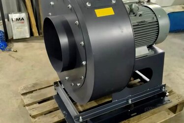
- Belt-pulley driven fan/pump: B3 foot, because feet and a base are needed for pulley alignment.
- Directly coupled pump: B3 or B35 according to the machine interface; B35 for dual support in heavy groups.
- Monoblock centrifugal pump: B5 large flange, motor bolts directly to the pump body.
- Small gearbox/variator: B14 small flange, for a compact connection.
- Vertical-shaft deep-well/process pump: V1, flange on top, shaft down.
- Mixer/agitator (shaft-up drive): V3 or V6.
In geared groups the mounting type must match the input interface of the gearbox; in monoblock geared motor selection, the input flange is checked as much as the output speed and torque. The monoblock geared motor purchasing article explains the correct choice on this. Reading the mounting letter correctly in the order type code is also important; the order and type code decoding in IE3 motors article shows how the mounting letters appear within the order code.
Error-Free Order Checklist
- Is the mounting code (IM B3 / B5 / B14 / B35 / V1 / V3 ...) clearly determined?
- If flanged, do the flange code and dimensions (pitch diameter, outer diameter, spigot diameter) fit the machine?
- Are the shaft diameter, shaft length and keyway suitable for the element to be connected?
- If vertical, are the shaft direction (down/up) and the seal/bearing configuration correct?
- Is the terminal box orientation suitable for the panel side?
- Are the frame size, power and efficiency class (IE3/IE4) consistent with the target?
Completing this list before ordering largely eliminates the "the motor arrived but did not fit" problem in the field. For terminal box orientation, the motor terminal box orientation and cable entry side article explains the correct choice according to the panel side.
Frequently Asked Questions
What is the difference between B5 and B14 flange?
Both are flanged mountings; the difference is in the flange size and hole type. B5 is the large flange (FF) and its holes pass outside the flange, the bolt connecting from outside the flange. B14 is the small flange (FT) and its holes are tapped, the screw threading from inside the flange. B5 is generally used at larger powers and heavy connections, B14 in small-power compact applications. Whichever flange type the machine to be connected has is the one chosen.
Can I convert a motor of the same power from B3 to B5?
In most motor families different mounting versions are produced for the same power and frame; however, this requires changing the front cover (flanged cover) of the motor. Some motors come with a multi-mount (universal) frame and allow both foot and flange connection. The correct approach is to order the mounting code suited to the need from the start or to prefer a universal frame.
Why is a special seal needed in vertical mounting?
When the shaft faces down (V1/V5), gravity and liquid from the application are directed toward the seal region; a standard horizontal seal may not provide full sealing in this position. Therefore vertical motors are generally ordered with an extra oil seal, suitable bearing preload and, if needed, a protective canopy. The shaft direction must always be stated in the order.
The mounting type is the most concrete yet most often skipped parameter of an electric motor order. B3 holds by feet, B5 by a large flange, B14 by a small flange, B35 by both; V1/V3/V5/V6 define vertical positions. When the right IM code, the right flange dimension and the right shaft direction come together, the motor fits the field the first time. At HEM Motor we offer B3, B5, B14, B35 and vertical mounting versions together with flange dimensions and frame tables, with fast delivery from stock; we ensure error-free supply by verifying the mounting code and machine interface together in your order. Contact us for motor supply with the correct mounting type and get a tailored quote and technical support.