English
 Türkçe
Choosing the right reducer is the foundation of a machine running smoothly, quietly and for a long life. A wrongly chosen reducer either cannot provide the desired output speed, cannot meet the required torque, or overheats and fails in a short time. Yet reducer selection can be done systematically by clarifying a few basic parameters in order. In this comprehensive guide we cover reducer selection step by step: finding the reduction ratio from the desired output speed, calculating the required output torque, determining the right reducer type, applying the service factor, choosing the mounting position and considering efficiency. In the end you will have a clear road map to define your need correctly and reach the most suitable reducer.
Step 1: Determine the Desired Output Speed
Every reducer selection begins with at what speed the driven end of your machine must turn. A mixer, conveyor, crane or feed auger wants to run at a certain output speed (rpm). A reducer cannot be selected without clearly determining this target output speed.
Example: If a conveyor belt's drive drum must turn at 45 rpm, your target output speed is 45 rpm. If you want to evaluate the low-speed direct-drive alternative, see our low-speed high-pole motors article; in some applications a gearless solution is also possible.
Step 2: Calculate the Reduction Ratio (i)
The reduction ratio is a simple ratio: motor input speed divided by desired output speed.
Reduction ratio (i) = Motor speed / Desired output speed
A standard 4-pole motor turns at roughly 1400 rpm. If your target output speed is 45 rpm: 1400 / 45 ≈ 31. So you need roughly a 1/30 reduction ratio. In worm gear reducers, common ratios range from 1/7.5 to 1/100 (such as 1/10, 1/20, 1/30, 1/50, 1/80, 1/100). Choosing the standard ratio closest to your target speed both eases supply from stock and optimizes cost.
Important: The real output speed differs slightly according to the motor's real speed under load (~1440 rpm rather than 1500 due to slip). We cover this topic in our slip and real speed in asynchronous motors article. You can find a practical example of the ratio-output speed relationship in our 220V single-phase geared motor output speed article.
Step 3: Determine the Required Output Torque
A reducer increases torque while reducing speed. The torque (Nm) your machine needs at the output shaft is the second critical parameter of reducer selection. If insufficient torque capacity is chosen, the reducer is strained, overheats and its life shortens.
You calculate the output torque from the force and distance the machine actually needs (for example drum radius and the pulled load). You can find torque calculation from motor power in our IE3 motor rated torque calculation article. The required power in pumps, fans and conveyors is covered in our motor power calculation article. The reducer's output torque must be above the real torque need you calculated.
Step 4: Choose the Reducer Type
After the ratio and torque are clear, you choose the reducer type according to the character of the application.
Worm Gear
90-degree-angled output, compact structure, self-locking capability. Economical at small and medium powers. Advantageous in applications requiring self-locking (for example the load must not run back); we examine this feature in our worm gear reducer self-locking article. For the product, see our worm gear reducers page.
Helical
High efficiency, in-line or staged structure; suitable for continuous and high-power applications.
Bevel-Helical
90-degree-angled, high efficiency and high torque. Preferred for heavy duty, continuous operation and large power. We cover the bevel-helical vs worm gear decision in our K Series bevel-helical vs worm gear article. For the product, see our helical worm gear reducers page.
Planetary
Very high torque in a compact frame; preferred in precise and high-torque drives.
Efficiency Comparison Between Reducer Types
Reducer type selection is important not only for torque and mounting but also for efficiency; because the reducer's efficiency determines how much of the power the motor produces is transferred to the output shaft. In worm gear reducers, especially at high reduction ratios, efficiency can be lower due to friction; this means less useful power at the output and more heat. Helical and bevel-helical reducers, on the other hand, usually offer higher efficiency.
This difference is negligible in short or occasional applications; but in drives running long hours per day, even continuously, it turns into a marked energy difference. So in a continuously running conveyor or mixer, a helical/bevel-helical reducer, although a bit higher in initial investment, can be more economical in the long run. We cover the cumulative gain when an efficient motor and reducer are used together in our using an IE4 motor with a reducer article. You can find reducing transmission loss with the right coupling selection and shaft alignment in our coupling selection and shaft alignment article.
Step 5: Apply the Service Factor (SF)
The service factor expresses the safety margin of the reducer according to the real operating conditions. A low service factor is needed under steady continuous load; a high service factor under shock, frequent start-stop or heavy load. For example, a crusher application running long hours per day with shock load requires a higher service factor than a calm mixer.
- Low service factor: Continuous, steady, shock-free load (fan, calm mixer).
- Medium service factor: Variable load, occasional start-stop (conveyor).
- High service factor: Shock, frequent start-stop, heavy load (crusher, press).
Applying the service factor correctly lets you enlarge the reducer's torque capacity you calculated according to real conditions; this means long life and reliability. For the heating limit on the motor side in frequent start-stop applications, also see our starts per hour article.
Step 6: Mounting Position and Output Shaft
How the reducer connects to the machine (mounting position M1-M6) and the output shaft type (solid shaft, hollow shaft/sleeve) complete the selection. The mounting position also affects the reducer's lubrication method; a wrong position can cause a lubrication problem. We detail this topic in our reducer mounting positions and lubrication article.
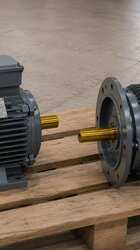
Step 7: Match the Motor to the Reducer Correctly
Reducer selection is completed with the motor that will connect to it. The motor's IEC frame size and flange type (B5/B14) must fit the reducer's input connection. You can find which motor fits which reducer in our worm gear and NMRV reducer motor matching article. We cover the gain of an efficient motor + reducer combination in our using an IE4 motor with a reducer article. You can review suitable motors for the reducer on our efficient electric motors page.
Whether you should buy the motor and reducer separately or as a monoblock is also a decision; we cover this in our geared motor vs separate motor + reducer article and our monoblock geared motor purchasing article.
Step 8: Consider Efficiency
In continuously running applications, reducer efficiency directly affects energy cost. Helical and bevel-helical reducers are usually more efficient than worm gears; over long operating hours this efficiency difference turns into energy savings. For an economical decision, evaluate the initial investment, efficiency and the application's operating hours together. You can find all the factors affecting geared motor price in our worm gear reducer price factors article.
Common Selection Mistakes
A few repeated mistakes in reducer selection negatively affect both cost and reliability. Knowing them in advance makes the right decision easier.
- Looking only at output speed: Finding the right ratio is not enough; if output torque and service factor are ignored, the reducer is strained under load.
- Skipping the service factor: A reducer chosen with a low service factor under shock load fails in a short time. Defining the load character correctly is essential.
- Motor-reducer incompatibility: If the IEC frame and flange type are chosen incompatibly, a mounting problem arises; sometimes an extra adapter is needed.
- Ignoring the mounting position: A wrong position leads to a lubrication problem and early wear.
- Not considering efficiency at all: In a continuously running application, a low-efficiency reducer spends extra energy over the years.
To avoid these mistakes, the safest method is to make the selection step by step, clarifying the parameters in order. To prevent the wrong motor from arriving, our nameplate matching article is a guide, and for warranty coverage our electric motor warranty article.
Geared Drive or Low-Speed Motor?
In some applications the desired low output speed can be achieved with a directly low-speed (high-pole) motor instead of a reducer. 6, 8 or 12-pole motors offer speeds around 1000, 750 or even 500 rpm without a reducer. This means mechanical simplicity and less maintenance; but when very low speed and high torque are needed, a reducer is unavoidable. The decision depends on the required output speed and torque level: a high-pole motor for moderately low speed; a geared drive for very low speed and high torque. We cover this comparison in our low-speed high-pole motors article and very low-speed applications in our 12-pole very low-speed motor article.
Quick Selection Summary
- Output speed: How many rpm does your machine want?
- Ratio: Motor speed / output speed.
- Torque: Required Nm at the output shaft.
- Type: Economical/compact → worm gear; efficiency/high torque → bevel-helical/helical.
- Service factor: Safety margin according to load character.
- Mounting: Position (M1-M6) and output shaft type.
- Motor: IEC frame and flange fit, efficiency class.
For step-by-step electric motor selection, see our electric motor selection guide and for basic terms our electric motor terms glossary. You can reach all our products and services from our home page.
Frequently Asked Questions
How do I calculate the reduction ratio?
The reduction ratio is found by dividing the motor input speed by the desired output speed. For example, for a 1400 rpm motor and a 70 rpm target output speed the ratio is 1400/70 = 20, that is 1/20. Choosing the standard ratio closest to your target speed eases supply from stock. The real output speed may differ a little due to the motor's slip under load.
Which reducer type should I choose?
For an economical, compact and self-locking solution a worm gear is suitable; for continuous heavy applications requiring high efficiency and high torque a bevel-helical or helical reducer is suitable. The decision depends on the application's load character, operating hours and budget. It is correct to make the type choice after the ratio and torque are clear.
Why is the service factor important?
The service factor determines the reducer's safety margin according to real operating conditions (shock, frequent start-stop, heavy load). A reducer chosen with an insufficient service factor is strained, overheats and fails early. Applying the correct service factor ensures the reducer runs long-lived and reliably; that is why defining the load character correctly is critical.
Get a Quote
Let us determine the most correct reducer together according to your application's output speed, torque and load character. For a quote with the right ratio, type, service factor and motor match, reach us at +90 (532) 345 49 86 or via our contact page. Our engineering team analyzes your need and offers a fast-delivery-from-stock solution.
Reducer Selection Checklist
- Is the output speed (rpm) your machine wants clear?
- Has the reduction ratio (motor speed/output speed) been calculated?
- Has the required torque (Nm) at the output shaft been determined?
- Has a reducer type suitable for the load character been chosen?
- Has the service factor been applied according to the operating condition?
- Have the mounting position (M1-M6) and output shaft type been determined?
- Have the motor's IEC frame/flange fit and efficiency class been checked?