English
 Türkçe
In an electric motor order, there is a detail as practically important as power, speed, frame size and mounting position but most often noticed at the last moment: the orientation of the terminal box and the cable entry side. The terminal box is the box where the motor's supply cable is connected, and it is located on top of the motor as standard; however, it can also be ordered rotated to the right or left. If the panel and cable route are on one side of the motor while the terminal box remains on the opposite side, the cable has to be run around the motor; this both complicates the installation and creates problems in terms of appearance and safety. This article covers the top, right and left positions of the terminal box orientation, the selection of the cable entry direction and gland side, the rotatable box feature, IP protection and gland compatibility, and the importance of stating this information in the order.
What Is the Terminal Box and Why Does Its Position Matter?
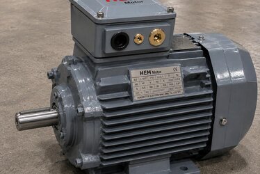
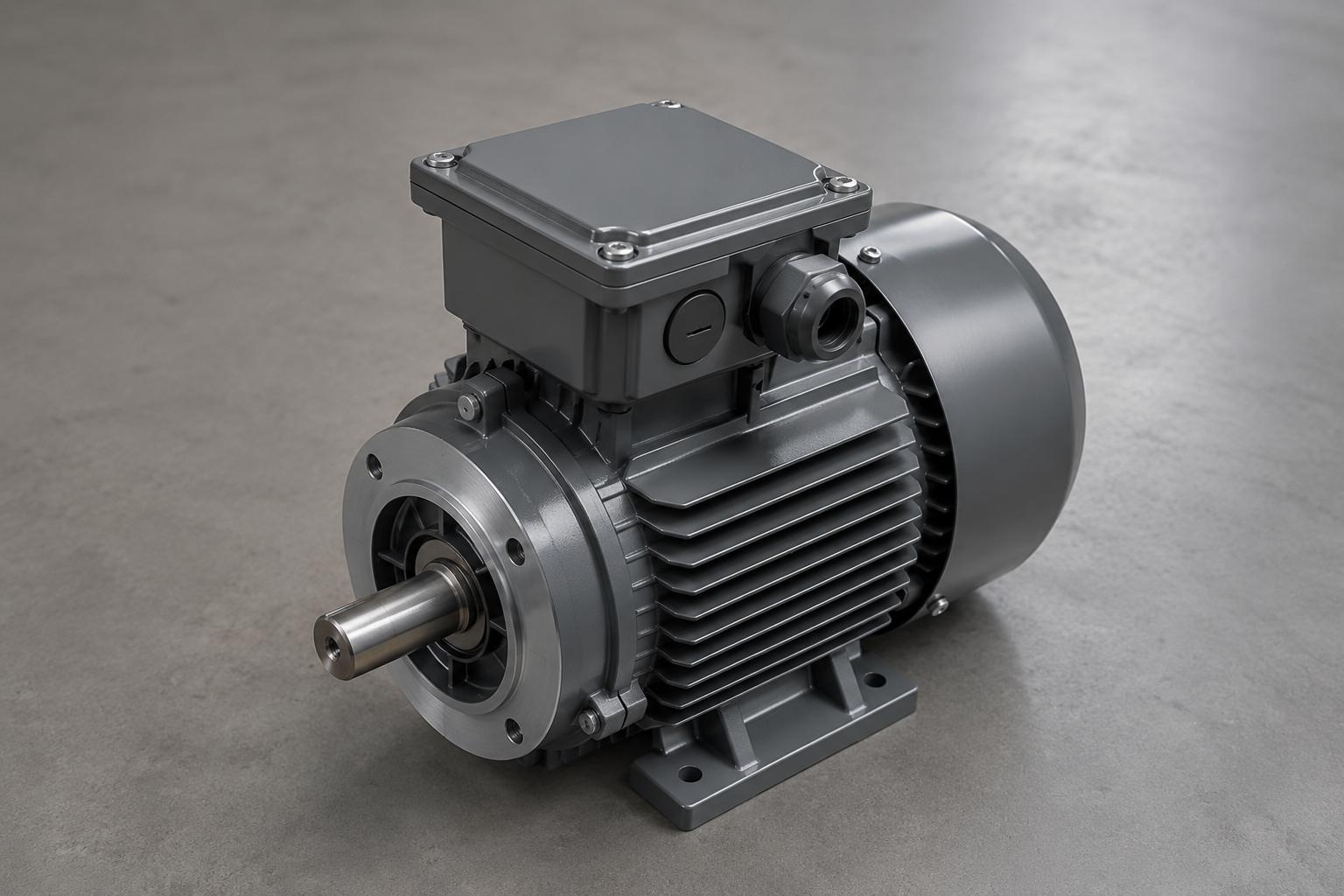
The terminal box is the protective box where the ends of the motor windings come out and the supply cable is connected. It contains the terminal connection block; here the motor leads are bridged and the grid cable is connected. The star or delta connection bridging is also done in this box; we covered terminal bridging and voltage selection in detail in our terminal connection and voltage selection article.
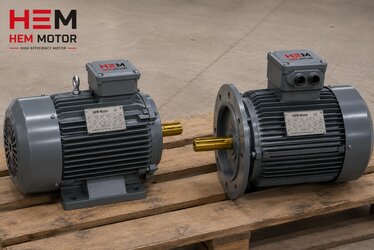
The position of the terminal box is on top of the motor as standard; this allows the cable to be taken from the top in most horizontal (foot-mounted B3) installations. However, in the field the panel and cable tray may not always be above the motor. If the panel is to the left of the motor, it is possible to take the cable from the shortest and tidiest route by rotating the terminal box to the left. This detail makes a big difference in terms of installation ease and tidy cabling, especially in tightly arranged facilities and in serial machine manufacturing. We covered the relationship of the terminal box and cable connection with IP protection and gland selection in our motor terminal box and cable connection article.
Top, Right and Left Position (Clock Position Notation)
The orientation of the terminal box is generally expressed by a clock position when looking at the motor from the shaft side. The standard positions are:
- Top position (standard): The terminal box is on top of the motor, facing up when the shaft is horizontal. This is the default factory position and the cable is taken from the top.
- Right position: When viewed from the shaft side, the terminal box is on the right. Preferred when the panel is to the right of the motor.
- Left position: When viewed from the shaft side, the terminal box is on the left. Preferred when the panel is to the left of the motor.
Although this position notation is standardized, clarifying which reference (viewed from the shaft side or the fan side) it is stated by when ordering prevents confusion. The safest method is to clearly state which direction you want the terminal box to face (for example, left when viewed from the shaft side). To prevent misunderstandings, the nameplate and order matching method in our prevent the wrong motor from arriving article also applies here.
Cable Entry Direction and Gland Side
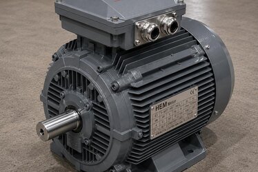
As important as the orientation of the terminal box is the side from which the cable enters the box. There is a hole on the terminal box for the gland (cable connection element) through which the cable passes. This gland hole is usually on one side surface of the box and can be brought to different directions by rotating the box or turning the cover. The cable entry direction is chosen according to the cable route in the facility: if the cable comes from below, the gland should face down, and if it comes from the side, it should face the side.
Choosing the gland side correctly ensures the cable is connected smoothly and without strain, without sharp bends. A gland in the wrong direction can lead to strain on the cable, wear of the cable insulation and loss of gland sealing. Especially in outdoor and humid facilities, the gland facing down prevents water from entering the box along the cable. We address the gland and IP protection relationship shortly. We covered cable cross-section, fuse and connection sizing in our rated current, cable, fuse and contactor selection article.
Rotatable Terminal Box
In many standard motors, the terminal box is designed to be rotatable to 4 different directions (top, right, bottom, left). This means the box can be connected to the body in different positions in 90-degree steps. A rotatable box provides the flexibility to turn the terminal box to the appropriate direction according to the panel and cable route during installation in the field. This feature makes it possible to reposition the terminal box especially when the motor mounting position changes (for example, in the transition from B3 to B5 or to vertical mounting).
However, the box may not be rotatable in every motor, or rotation may be limited to certain steps. For this reason, stating the desired terminal box orientation in the order is safer than relying on rotation in the field. When the box is rotated, the terminal connection arrangement and bridging inside must also be checked, and the rotation direction and phase sequence must be verified; we covered rotation direction and phase sequence in our motor rotation direction and phase sequence article.
IP Protection and Gland Compatibility
The terminal box is where the motor's electrical connection is protected against external factors; therefore the IP protection class of the box and gland must be compatible with the motor as a whole. In a dusty or humid environment, the terminal box of an IP55-class motor must also provide at least IP55 sealing. The gland (cable connection element) provides sealing at the point where the cable enters the box; a gland of the wrong size or not properly tightened nullifies the protection class and lets dust or water in.
In gland selection, a size suitable for the cable diameter should be chosen and unused holes should be closed with blind plugs. We covered IP protection class selection in our IP protection class selection (IP55, IP65, IP66) article, and the need for advanced protection in hygienic and outdoor environments requiring high-pressure washdown in our IP69K washdown and hygienic facility article. We examined the dust sealing of the terminal box in dusty crusher and mine sites in our dust sealing in crusher motors article. The motor's grounding connection is also made in the terminal box; we covered grounding and electrical safety in our grounding and electrical safety article.
Correct Ordering by Panel Side
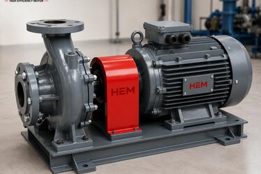
The basic logic of selecting the terminal box orientation and cable entry side is to choose the shortest, tidiest and safest cabling route according to the motor's position in the facility and the panel route. At the ordering stage, the following questions must be answered: In which mounting position (B3/B5/V1) will the motor be connected to the machine? On which side of the motor are the panel and cable tray? Will the cable come to the motor from below, the side or the top? These answers determine which direction the terminal box will face and which side the gland will be on.
The mounting position (IM code) and the terminal box orientation must be considered together; because when the motor is rotated, the orientation of the terminal box also changes. We covered the mounting position codes in detail in our reading motor IM mounting codes article. We compiled the information that should be provided when requesting a quote in our 8 pieces of information when requesting a quote article; the terminal box orientation should also be added to this information. You can find the connection and first-startup checks during commissioning in our commissioning and first startup checklist article. You can review our product range in the industrial general-purpose motors category.
Frequently Asked Questions
Can I rotate the terminal box myself in the field?
In many standard motors, the terminal box can be rotated to 4 directions (top, right, bottom, left) in 90-degree steps; in that case you can turn it to the appropriate direction in the field. However, this may not be possible in every motor, and during rotation the terminal connection arrangement, bridging and sealing inside must remain correct. After the box is rotated, the gland sealing and IP protection must be checked and the rotation direction verified. The safest method is to state the desired direction in the order and not rely on rotation in the field.
Does the terminal box orientation affect the motor's operation?
The orientation of the terminal box does not directly affect the motor's electrical or mechanical performance; what it affects is installation ease, cabling tidiness and sealing. A box in the wrong direction strains the cable and leads to unnecessary cable length and sharp bends; this poses a risk to the cable insulation and gland sealing in the long term. Also, a gland facing the wrong direction (for example, up) can cause water to enter the box along the cable outdoors. So the orientation matters more for safety and installation than for performance.
How should I state the terminal box orientation in the order?
The clearest method is to state the reference point and the desired direction together: for example, the terminal box in the left position with the gland facing down when viewed from the shaft side. Also stating the motor mounting position (IM code) and which side the panel is on relative to the motor makes it easier to determine the correct position. Adding the cable entry direction (down/side/top) also ensures the gland side is chosen correctly. This information should be provided together with power, speed and frame size.
Get a Quote
Our expert team will guide you in correctly ordering your motor with the terminal box orientation and cable entry side suitable for the panel and cable route in your facility. For support on mounting position, terminal box orientation, gland side and IP protection, reach us through our contact page or by phone at +90 (532) 345 49 86. For more technical content, visit our home page and our industrial general-purpose motors category.
Order Checklist
- Determine the motor mounting position (IM B3/B5/V1); the terminal box orientation changes with it.
- Identify which side the panel and cable tray are on relative to the motor.
- State the desired terminal box orientation with a reference (e.g. left when viewed from the shaft side).
- Determine which direction the cable will come to the motor from (down/side/top).
- Choose the gland (cable entry) side according to the cable route; have the gland face down outdoors.
- Verify that the IP protection class of the terminal box and gland is compatible with the motor.
- Choose the gland size suitable for the cable diameter; close unused holes with blind plugs.
- Find out whether the box is rotatable and what the rotation steps are.
- Check that the grounding connection is made correctly in the terminal box.
- Add this information to the order together with power, speed, frame size and mounting code.