English
 Türkçe
When ordering an electric motor, there is one piece of information as important as power, speed and frame size but often overlooked: the mounting position, that is, the IM code. The IM (International Mounting) code defines how the motor will be mounted, whether it is foot-mounted or flange-mounted, and whether the shaft will be positioned horizontally or vertically, using a standard notation. A motor ordered with the wrong mounting code cannot be physically connected to the machine; if a flange-mounted motor arrives where a foot-mounted one was expected, or a shaft-down motor arrives where shaft-up was expected, work stops, the motor is returned and the lead time slips. This article explains the IM codes in the IEC 60034-7 standard, the most common IM B3, IM B5, IM B35, IM B14, IM V1 and IM V5 positions, and why correctly stating the mounting position in the order is critical.
What Is the IM Code? IEC 60034-7 Standard
The IM code is an international standard that defines the mounting arrangement and shaft position of a motor. The IEC 60034-7 standard defines these codes in two different notations: Code I (a letter and number combination, e.g. IM B3) and Code II (fully numerical, e.g. IM 1001). In practice, the Code I notation is the most widely used in the industry. The IM code expresses with a single short code whether the motor is foot-mounted or flange-mounted, which direction the shaft faces, and whether the motor is mounted horizontally or vertically.
The purpose of this standardization is to provide a common language between different manufacturers and different countries. When a machine manufacturer wants the motor to be IM B5, the same flange-mounted position is understood everywhere in the world. This prevents misunderstandings and enables correct ordering. The mounting type is directly related to the connection surface of the motor; we covered the basic logic of connection types in our B5 flange or B14 flange article. We explained the general method of preventing the wrong motor from arriving in our prevent the wrong motor from arriving article.
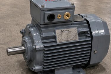
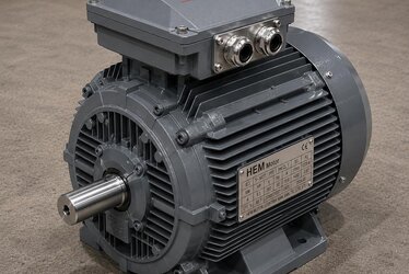
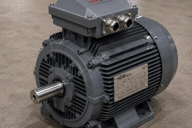
IM B3: Foot Mounting
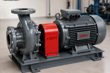
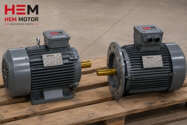
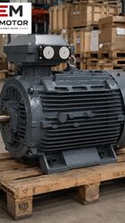
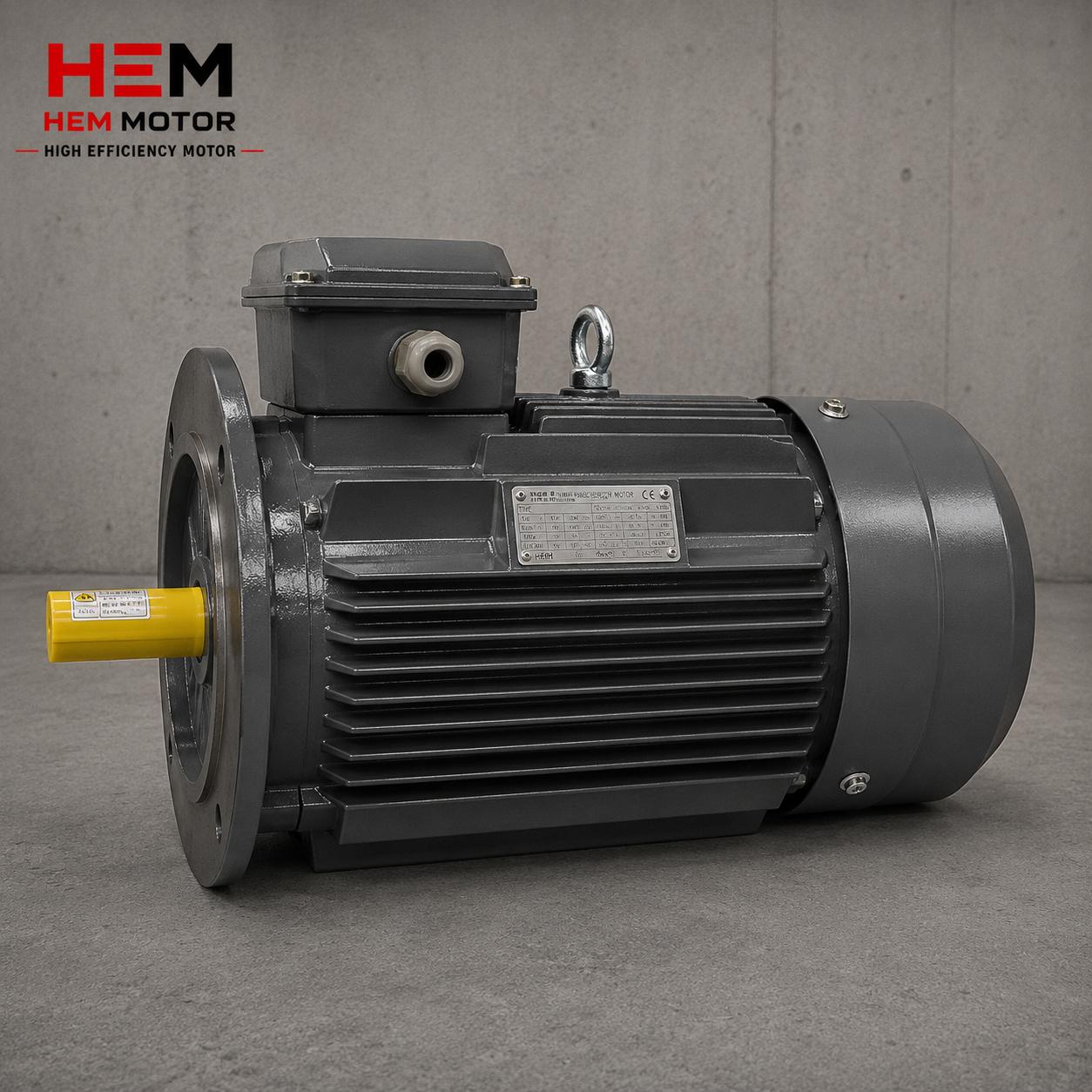
IM B3 is the most common and best-known mounting position. In this position, the motor is bolted to a base, frame or floor through the feet under its body. The shaft is horizontal and the motor usually transmits drive to the machine through a belt-pulley, coupling or gearbox connection. IM B3 motors are used in a very wide range of applications, from conveyors to pumps, from fans to generators.
The advantage of a foot-mounted motor is that it can be securely fixed to a solid base and, when needed, placed on a slide base for belt tensioning. The mounting and connection features of B3 foot-mounted motors can be found in detail in the catalog; the suitability of foot-mounted motors for belt-pulley, coupling and gearbox connections is a standard feature. We covered the shock and vibration resistance of foot mounting in heavy-duty cast-iron applications in our impact resistance in cast-iron motors article.
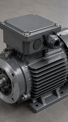
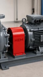
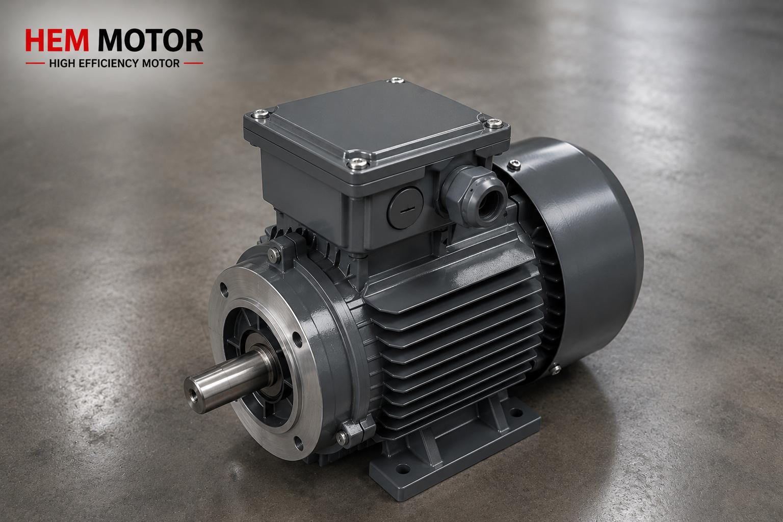
IM B5 and IM B14: Flange Mounting
Flange-mounted motors connect directly to the machine, gearbox, pump or fan through a flange on the front cover instead of feet. There are two basic flange types:
- IM B5 (large flange): The large-diameter flange on the front cover is connected with holes and bolts on the flange. It is generally used for direct coupled connection to a gearbox, pump and fan housing. The power range is wide and it is also preferred at high power.
- IM B14 (small flange, face flange): A smaller-diameter flange with threaded holes. It is generally used in small and medium-power applications, in compact gearbox and machine connections.
The advantage of flange mounting is that it allows the motor to be connected directly and with precise alignment to the machine; it requires no intermediate base or additional alignment. The choice between B5 and B14 is made according to the flange type of the machine to be connected, and these two are not interchangeable. We detailed the difference between B5 and B14 and the correct choice for machine manufacturers in our B5 or B14 connection type selection article. For the flange and frame matching suitable for the gearbox, our motor matching for worm gear reducers article is a basic reference.
IM B35 and IM B34: Foot + Flange Combination
In some applications, both foot and flange connection are wanted together. These combined mounting types are:
- IM B35: The combination of a B3 foot connection with a B5 large flange. The motor is both fixed to the frame by its feet and connected to a gearbox, pump, fan or machine body by its front large flange. This dual connection gives the motor additional mechanical strength and alignment assurance.
- IM B34: The combination of a B3 foot connection with a B14 small flange. It is used at smaller powers, in applications where both fixing by feet and connection to a machine surface by a small flange are wanted.
B35 mounting is preferred especially in applications connected to a gearbox that also need additional support under vibration or heavy load. Because while the flange connection provides alignment, the feet give the motor additional carrying and fixing support.
IM V1 and IM V5: Vertical Mounting
In addition to horizontal mounting, some applications require the motor to be positioned vertically. Vertical mounting codes indicate the shaft direction:
- IM V1: Flange-mounted vertical mounting with the shaft facing down. Vertical pumps and mixers that drive from top to bottom are used in this position. It is the most common vertical mounting position.
- IM V5: A foot-mounted (wall-mounted) or shaft-down vertical mounting variant; it varies by application.
- IM V3 / IM V6: Vertical mounting positions with the shaft facing up.
A critical issue in vertical mounting is the correct selection of the oil seal and sealing in cases where the shaft faces down (V1); because gravity can push oil and moisture toward the shaft bearing. We covered the oil seal and correct ordering in vertical mounting in detail in our vertical motor selection (V1/V5) article. In vertical mounting, a protective drip cover against rain and dust on top may also be needed.
Selecting the Correct Mounting Position by Machine
Which IM position is chosen depends entirely on the machine and application the motor will be connected to. The foot (B3) position is suitable for most horizontal applications where the motor is fixed to a base and transmits drive by belt-pulley or coupling. The flange (B5/B14) position is chosen for applications where the motor is directly coupled to a gearbox, pump or fan. The combined (B35) position is preferred in heavy or precisely aligned applications that require both foot and flange support. The vertical (V1/V5) position is required for vertical pumps, mixers and special machine arrangements.
When replacing an existing motor, the mounting position must be identified exactly from the old motor's nameplate and physical connection; otherwise the new motor cannot be connected to the machine. We covered matching the mounting position when replacing an old-brand motor with an equivalent in our replacing an old-brand motor exactly and equivalent selection and IEC connection dimensions articles. We examined mechanical compatibility (frame, foot, shaft) in the transition to an efficient motor in our mechanical compatibility in the transition to IE4 article.
The Importance of Stating the Mounting Position in the Order
Stating the IM code in a motor order is as important as power and speed. Because a motor of the same power and frame size is produced in different mounting positions as B3, B5, B35 or V1, and these cannot be used interchangeably. If the mounting code is not stated in the order, the motor that arrives may not be physically connectable to the machine. This means return, reorder and lead-time delay. We compiled the information that should be provided when requesting a quote in our 8 pieces of information when requesting a quote article, and pre-order nameplate matching in our prevent the wrong motor from arriving article. You can find the path to motor types and the correct model in our electric motor types and purchasing map article. You can review our product range in the industrial general-purpose motors category.
Frequently Asked Questions
What is the difference between IM B3 and IM B35?
IM B3 is foot mounting only; the motor is connected to a base by the feet under its body and the shaft is horizontal. IM B35 is the combination of both foot (B3) and large flange (B5) mounting; the motor is both fixed to the frame by its feet and connected to a gearbox or machine by its front large flange. B35 combines the precise alignment provided by the flange connection with the additional mechanical support provided by the feet; this is why it is preferred in heavy applications connected to a gearbox that need additional support.
Can I mount an IM V1 motor horizontally?
It is generally not recommended. An IM V1 motor is designed for vertical operation with the shaft facing down; lubrication, bearing load distribution and the oil seal are selected for this position. If mounted horizontally, the bearing load and lubrication will differ from what is expected and the life may be shortened. If the motor will be used both horizontally and vertically, this must be stated in the order and a suitable mounting position that the manufacturer will approve must be selected. Since changing the mounting position affects the motor's bearing and lubrication design, it should not be changed arbitrarily.
Is it enough to give only kW and speed in the order?
No. kW and speed determine the electrical characteristics of the motor but not its mechanical connection. A motor of the same kW and speed is produced in different mounting positions as B3, B5, B35, B14 or V1. If the mounting code (IM) is not stated, the motor that arrives may not be connectable to the machine. For a correct order, the kW, speed, frame size and mounting position (IM code) must be given together; shaft diameter, protection class and voltage should also be added.
Get a Quote
Our expert team will guide you in selecting the correct motor in the mounting position (IM B3, B5, B35, B14, V1, etc.) suitable for your machine. If you want to replace your existing motor with an exact equivalent or select a motor for a new application, reach us through our contact page or by phone at +90 (532) 345 49 86. For more technical content, visit our home page and our industrial general-purpose motors category.
Order Checklist
- Determine the mounting surface (foot or flange) of the machine the motor will connect to.
- Choose IM B3 for foot connection, IM B5 for a large flange, IM B14 for a small flange.
- If both foot and flange are needed, specify IM B35 (large flange) or IM B34 (small flange).
- In vertical mounting, determine the shaft direction: IM V1 for shaft down, V5/V3/V6 by application.
- If replacing an existing motor, verify the mounting position from the old nameplate and physical connection.
- In a vertical shaft-down (V1) application, make sure the oil seal and sealing are suitable.
- Always state the IM code together with kW, speed and frame size in the order.
- Also add shaft diameter, key size, protection class (IP) and voltage information.
- Verify that the flange type (B5/B14) exactly matches the machine flange.