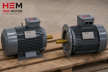
English
 Türkçe
It does not matter how high quality an electric motor is if the terminal connection is not made correctly. A significant share of motor failures and fire risks comes not from the motor itself but from a loose connection in the terminal box, a wrong cable lug or an incorrect tightening torque. A loose connection increases contact resistance; rising resistance leads to heating, and heating in time causes the terminal to darken and burn. In this guide we cover cable connection and cable lug selection on an electric motor step by step, in terms of terminal structure, lug type, correct cross-section, bolt tightening torque and heating risk. A correctly made connection carries current trouble-free throughout the rated life of the motor.
The Basis of Terminal Connection: Bridging and Voltage Selection
In the terminal box of a three-phase asynchronous motor there are six terminals: U1-V1-W1 and U2-V2-W2. These are connected in star (Y) or delta (Δ) with bridge plates. The bridging direction is set by the motor's supply voltage. A motor marked, for example, 230/400V is connected in star on a 400V supply and in delta on 230V. Wrong bridging causes the motor either to run at very low power or to draw excess current and burn. You can find correct bridging in detail in our electric motor terminal connection: star and delta bridging at 230/400V and electric motor star-delta wiring diagram articles. If star-delta starting will be applied, all six terminals are run separately; in that case the IE3 motor winding connection (star/delta) and voltage selection article clarifies the wiring.
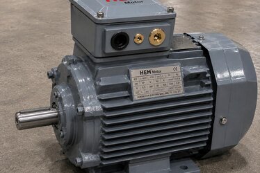
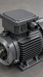
Terminal Box Orientation and Cable Entry Side
Before starting the connection, the terminal box orientation and which side the cable will enter must be planned. On most cast iron motors the terminal box can be rotated in 90-degree steps. A cable entry direction chosen wrongly for the panel side causes unnecessary bending of the cable and stress on the gland. On this subject the motor terminal box orientation and cable entry side selection article explains what to consider before ordering.
Cable Cross-Section and Current: Why Is the Right Section Critical?
The cable cross-section is selected according to the rated current the motor draws. A cable that is too thin overheats under current, creates voltage drop and fatigues its insulation. A cable that is too thick brings unnecessary cost and difficulty connecting to the terminal. The right section is set by the motor's rated current, the cable laying method, ambient temperature and distance. For rated current and the related cable/fuse selection, our IE3 motor rated current: cable, fuse and contactor selection article provides the basic calculation. To read the rated current from the motor nameplate, reading the IE3 motor nameplate: kW, speed, cosφ and efficiency helps.
On industrial motor supply lines, PVC-insulated cable of NYY type is generally used. Where fire safety is critical (crowded areas, escape routes) halogen-free, flame-retardant (LSZH) cables are preferred. The cable type must be chosen according to the temperature, humidity and mechanical stress of the environment. In VFD systems, shielded cable and correct grounding are essential; we cover this in the electric motor grounding and EMC: shielded cable in a VFD system article.
Cable Lug Types and the Right Choice
A cable lug is used to connect the end of a stranded cable to the terminal bolt safely and with low resistance. A stranded cable tightened directly without a lug loses its contact surface and clamping force over time as the strands spread. The main lug types are:
Ring lug: Passed by removing and refitting the terminal bolt, it is the safest type. Even if the bolt loosens the lug does not slip out; it is the most preferred type on motor terminals. Fork (U) lug: Can be slid in from the side without fully removing the bolt; it provides fast connection but its risk of slipping out on loosening is higher than the ring type. Tube (pin) lug: Gathers the stranded cable and lets it enter the terminal slot directly; it is used especially in screw-clamp terminals. In lug selection, the cable cross-section must match the lug hole and bolt diameter.
Lug Crimping and Correct Application
The lug is connected to the cable either by crimping or by screw clamping. In a crimp lug, the correct size of crimping tool and the right lug-section match are essential. An under-crimped lug leads to high resistance, an over-crimped one cuts the strands. After crimping, the lug must not pull off the cable when pulled by hand. In stranded cables, using a ferrule before clamping prevents the strands spreading. To preserve the terminal box IP protection and correct gland selection, review the motor terminal box and cable connection: IP protection and correct gland selection article.
Bolt Tightening Torque (Nm): Too Little Is Harmful, So Is Too Much
The most important factor that determines the life of a terminal connection is the correct tightening torque. If the tightening torque is too low the contact resistance stays high and the connection heats; if too high the bolt thread or brass terminal is damaged and cracks. There is a torque value set by the manufacturer for each terminal bolt size, and it must be applied with a torque wrench in Nm. Approximate values vary with size; for example a few Nm on small terminals, on the order of tens of Nm on large power motors. For the correct value, the motor manual and the terminal manufacturer's table must always be consulted.
After tightening, the connection should be rechecked a while after the first run (due to heat cycles). This should be part of the commissioning routine, especially on large high-current motors. For commissioning checks, the electric motor commissioning and first start-up checklist article is a comprehensive reference.
Loose Connection and Heating Risk: Symptoms
A loose or faulty terminal connection reveals itself: discoloration at the terminal (darkening, yellowing), a burnt insulation smell, abnormal temperature in the terminal box and occasionally behavior similar to single phasing in the motor. When the contact resistance of one phase rises, that phase weakens and the motor draws unbalanced current, which heats the winding. For symptoms, the single phasing (phase loss) in asynchronous motors: symptoms, burnout risk and protection article helps you recognize the warning signs. Assess the general heating causes of the motor together with the motor winding temperature monitoring: PT100 and PTC thermistor article. Voltage unbalance creates similar risks; the asynchronous motor derating under voltage unbalance article explains this effect.
Grounding and Electrical Safety
In a terminal connection, the grounding terminal is as important as the phase terminals. The motor body must be solidly grounded from the grounding screw in the terminal box; this provides personal safety against body leakage. The cast iron motor grounding and electrical safety article explains correct grounding. You can find the whole protection set in the electric motor protection: thermal relay and fuse selection and motor protection circuit breaker (MPCB) selection and setting articles. To request protection equipment together when purchasing, the electric motor protection equipment article is useful.
Contactor, Thermal Relay and Auxiliary Connections
The power connection at the motor terminal is completed on the panel side with a contactor and thermal relay. The contactor contacts and thermal connections must also be made with the correct cross-section and correct tightening torque; a loose connection inside the panel produces heating and faults just like at the motor terminal. For sizing the contactor and thermal relay according to the motor's rated current, the IE3 motor rated current: cable, fuse and contactor selection article gives the basic calculation. If a protection circuit breaker (MPCB) is used, the motor protection circuit breaker (MPCB) selection and setting article guides setting the trip current correctly.
In motors with star-delta starting, six terminals are run to the terminal box and the transition timing is set on the panel side; wrong timing leads to large current surges. You can find this setting in the asynchronous motor star-delta transition time and timer setting article. In motors running with a frequency drive, in addition to the terminal connection, the grounding of the shielded cable and protection against bearing current become important; we cover this in the VFD and harmonic-induced extra heating and bearing current in asynchronous motors article.
Terminal Box and Connection Selection by Environment
The quality of the terminal connection also differs by the environment the motor works in. In a dusty crusher or mine site, dust sealing of the terminal box; in a humid or chemical environment, corrosion-resistant glands and gaskets come to the fore. In environments requiring a high protection class, the cable entry must be made with a suitable IP-rated gland, and unused holes must be closed with blanking plugs. You can find protection class selection in the electric motor IP protection class selection article, and terminal sealing for a dusty site in the crusher motor dust sealing and IP65/IP66 protection article.
In an explosive environment (Ex zone) the terminal connection is subject to special rules; a certified cable gland, correct tightening and an approved connection become essential. Assess the explosion-proof motor requirement in the when is an explosion-proof (ATEX) motor essential article. Planning connection details such as the correct cable cross-section, lug and tightening torque at the ordering stage is important to avoid surprises in the field; for a purchasing map the electric motor types and purchasing map article guides you. To recognize general fault symptoms after connection, review the electric motor failures: symptoms and causes article.
Frequently Asked Questions
Can a motor be connected without a cable lug?
Single-strand thin cables can be connected directly, but in stranded cables using a lug (or at least a ferrule) is essential. A stranded cable tightened without a lug spreads over time, contact resistance rises, and the connection can heat and burn.
How tight should the terminal bolt be?
Each bolt size has an Nm torque value set by the manufacturer, and it must be applied with a torque wrench. Under-tightening causes contact resistance and heating, over-tightening causes thread and terminal damage. The correct value is in the motor manual.
Which lug type is safest on a motor terminal?
The ring lug is the safest type; even if the bolt loosens it does not slip out. The fork lug provides fast connection but has a higher risk of slipping out on loosening. In screw-slot terminals a tube (pin) lug is used.
Get a Quote
IE3 and IE4 motors delivered with the right terminal structure, cable entry and protection equipment make a fault-free field connection easier. Share the motor's power, voltage, starting method and cable entry side; let us determine the right motor together with the suitable terminal box orientation and protection package. For a fast quote reach us through our contact page or call +90 (532) 345 49 86. Browse our whole product range from our home page and the purchasing guide from our electric motor types and purchasing map article.
Connection and Selection Checklist
1) Read the rated current and voltage from the motor nameplate. 2) Choose the cable cross-section and type (NYY/halogen-free) according to current and laying conditions. 3) Plan the terminal box orientation and cable entry side according to the panel. 4) Make the correct bridging (star/delta) according to the 230/400V nameplate. 5) Choose the lug type suited to the cable cross-section and bolt diameter. 6) Use a lug or ferrule on stranded cable. 7) Crimp the crimp lug with the correct tool; verify with a pull test. 8) Tighten the terminal bolt to the manufacturer's specified Nm torque. 9) Connect the grounding terminal solidly. 10) Recheck connection tightness and terminal temperature after the first run.