 English
 Türkçe

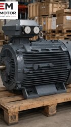
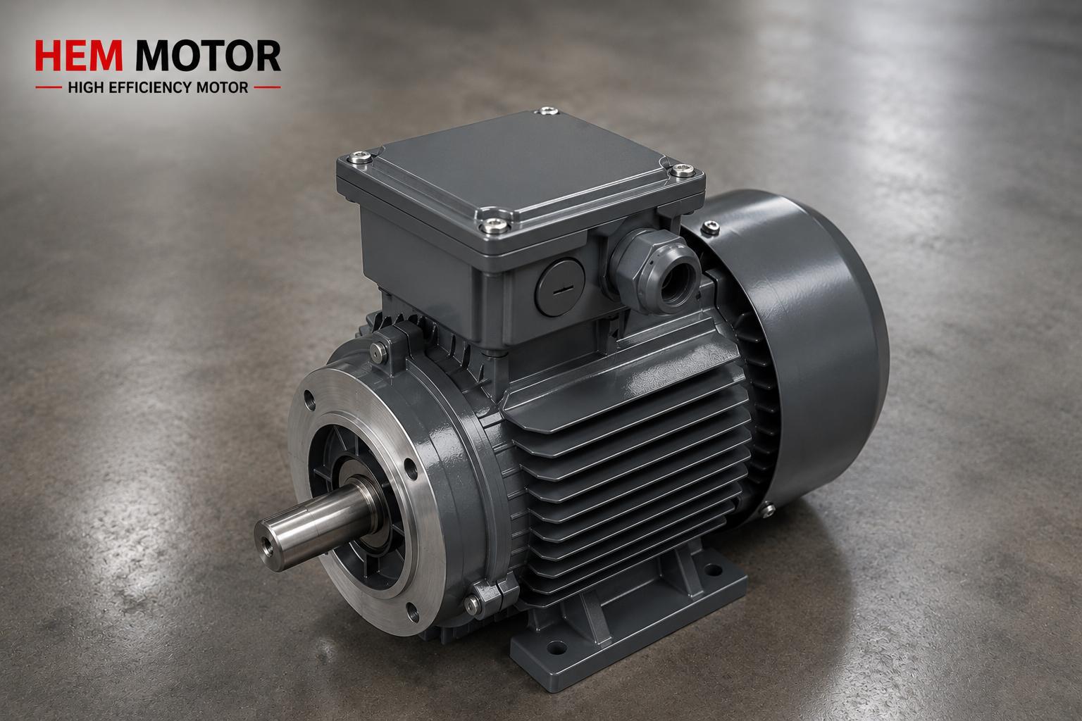

When you buy an IE3 electric motor, the job does not end once the motor reaches the panel; the real engineering begins with correctly sizing the electrical installation that will feed it. The starting point for that sizing is a single value: the rated current (In) printed on the nameplate. Misreading the rated current, or basing your design on the wrong voltage column, leads to a chain of problems — from an undersized cable to an overheating contactor, from a thermal relay that keeps tripping to a needlessly oversized breaker. In this article we explain what rated current is, why the nameplate lists different values for 230 V and 400 V, and how to size the cable, fuse, contactor and thermal relay step by step from that current.
The goal is to run the motor safely and continuously while providing both short-circuit and overload protection, without wasting budget on oversized components. A correctly engineered motor feeder extends motor life and prevents unexpected stoppages.
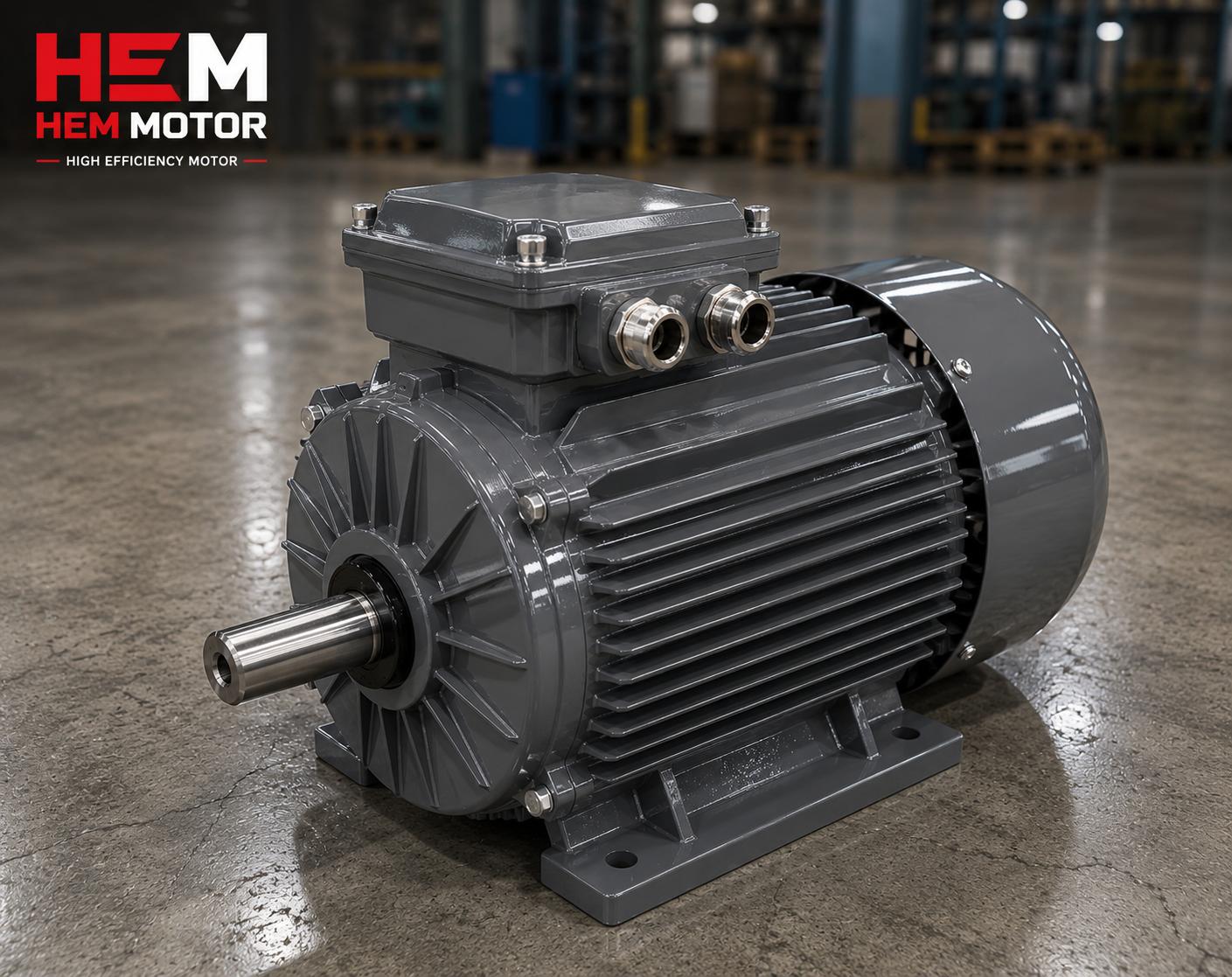
What Is Rated Current (In)?
The rated current is the current the motor draws from the grid when running continuously (S1 duty) at its nameplate rated power and rated voltage. This value represents normal operation, where the rotor turns and the load is met. Rated current is entirely different from the locked rotor current (LRA) at start-up; at start the motor draws typically 6-8 times its rated current, but only for seconds. The installation's continuous load capacity is set by the rated current, while the resistance to short-circuit and starting surge is set by separate criteria.
Rated current is determined together by power, voltage, power factor (cosφ) and efficiency. In a three-phase motor the current is roughly the power divided by the product of voltage, root-three, power factor and efficiency. So even at the same kW, a high-power-factor, high-efficiency IE3 motor draws a lower rated current than an old, low-efficiency motor. This is one of the hidden advantages of the efficient motor: lower current means smaller cable and breaker, and lower line losses.
Why Does the Nameplate List Two Currents? 230 V (Delta) and 400 V (Star)
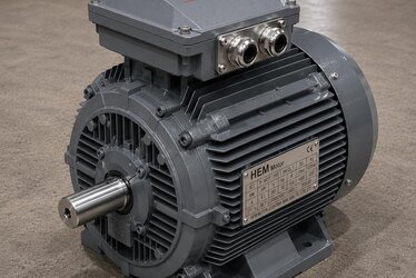
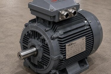
On a standard three-phase motor nameplate you usually see two voltage and two current values: for example one current for 230 V Δ (delta) and a lower current for 400 V Y (star). These two values describe how the motor is connected at different grid voltages. The same power is produced at both voltages; but as voltage rises, the current needed to deliver that power falls. Therefore the rated current in the 400 V star connection is about root-three (1.73) times lower than in the 230 V delta connection.
Because the standard low-voltage grid in Türkiye is 400 V (phase-to-phase), most industrial motors run on 400 V in star connection, and the installation is sized to the rated current on that line. Using the wrong nameplate line causes serious error: if you use the 230 V delta current for your 400 V line you oversize the installation and waste money; do the reverse and you dangerously undersize the cable and breaker. For the fundamentals of nameplate reading, our article on reading IE3 motor nameplate ratings clarifies the basics.
Do Not Confuse This With Star-Delta Starting
The Y/Δ notation on the nameplate describes the connection type and voltage suitability; this is a different matter from the star-delta starting method used at start-up. Star-delta starting is a technique to reduce starting current by first starting the motor in star and then switching to delta, and it applies only to motors that can run in delta at 400 V (i.e. nameplate marked 400 V Δ / 690 V Y). For starting methods and wiring, see our article on asynchronous motor star-delta and soft starter.
From Rated Current to Installation: Step-by-Step Sizing
Once the correct rated current is determined, the four core components of the feeder are selected in order. Each depends on the others; if one is wrong, the protection chain breaks.
- Cable cross-section: The cable must carry the rated current continuously while keeping temperature within safe limits. Cross-section is chosen by current, installation method (tray, suspended, underground), ambient temperature and line length. On long runs, voltage drop is also considered and the section is increased.
- Fuse / short-circuit protection: Protects the line and devices against short-circuit current. In a motor circuit the fuse is chosen to withstand the starting current (LRA) without tripping yet open quickly on a short-circuit — usually an aM-type fuse rather than gG, or a motor protection circuit breaker.
- Contactor: The power switch that starts and stops the motor. It is sized by the rated current and the AC-3 utilization category, i.e. the harsh conditions when the motor is switched in and out under load.
- Thermal relay (overload protection): Protects the motor against sustained overload and phase loss. The setting current is matched to the motor's nameplate rated current, so that if the current exceeds In for a certain time the relay opens.
Considerations in Cable Cross-Section Selection
Looking only at current-carrying capacity is not enough in cable selection. High ambient temperature, cables laid in bundles side by side, and the installation method all reduce the current the cable can carry; in that case derating factors are applied and the section is increased. In addition, voltage drop becomes critical on long feeders: if insufficient voltage reaches the motor, torque drops, current rises and the motor overheats. So on long runs the cross-section is set by the voltage-drop criterion rather than the current criterion.
Contactor and Utilization Category (AC-3)
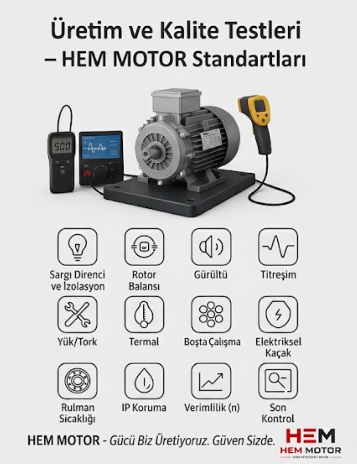
The most common mistake in contactor selection is looking only at the current value and ignoring the utilization category. The correct category for motor loads is AC-3. This category defines the demanding switching conditions of the contactor energizing the motor under starting current and breaking a running motor. A contactor selected by its AC-1 (resistive load) value wears its contacts out very quickly on a motor load. Therefore the contactor is selected from the table by motor power and AC-3 current; in frequently switched applications, choosing one size larger extends life.
Thermal Relay and Phase Protection
The thermal relay is the first line of defense against overload and phase loss, one of the most common causes of motor failure. Its setting is brought to the motor's rated current. If a phase is lost, the current drawn from the remaining phases rises; the thermal relay senses this increase and stops the motor, preventing the winding from burning out. On more critical and larger motors, in addition to the thermal relay the winding temperature is monitored directly with a PTC thermistor or PT100. We cover the full set of motor protection equipment in our article on electric motor protection: thermal relay and fuse selection.
The IE3 Motor's Current Advantage: More Efficient, Lower Current
At the same kW, an IE3 motor generally runs with a lower rated current and higher power factor than a lower-efficiency-class motor. This reduces both the continuous copper losses in the line and the reactive power demand. In practice this means somewhat lower cable and breaker cost in an installation upgrade, a lighter compensation burden, and a cleaner load reflected to the grid. To evaluate the total return of an efficient-motor investment, you can review HEM's range and stock options for electric motors.
Practical Selection Flow
- 1. Read the nameplate: Base your design on the rated current line corresponding to your field voltage (usually 400 V).
- 2. Select the cable: Determine the section from rated current + ambient temperature + installation method + line length (voltage drop).
- 3. Select short-circuit protection: A fuse or motor protection breaker that does not trip on starting current but opens fast on a short-circuit.
- 4. Select the contactor: In the AC-3 category, matched to motor power; one size larger for frequent switching.
- 5. Set the thermal relay: Setting current = the motor's rated current; prefer a phase-loss protected type.
When these five steps are applied correctly, the motor runs safely, the protection chain is complete, and budget is not wasted on oversizing. To request a quote with the right motor and appropriate rated values, you only need to clarify your application's power, voltage and speed.
Frequently Asked Questions
The nameplate lists two currents — which should I use?
Use the value corresponding to your field voltage. Since the standard grid in Türkiye is 400 V, the motor usually runs in 400 V star connection and the installation is sized to the lower current on that line. The 230 V delta value applies only on systems with 230 V line-to-line voltage, or for the delta stage in star-delta starting.
What current should I set the thermal relay to?
The thermal relay setting is matched to the motor's rated current (In) at the operating voltage. The motor runs continuously below In; the relay opens when the current exceeds In for a certain time, protecting the motor from overload and phase loss. Setting it needlessly high renders the protection useless.
Does an IE3 motor draw lower current?
Generally yes. At the same kW, an IE3 motor draws a lower rated current than a lower-efficiency-class motor thanks to higher efficiency and power factor. This means smaller cable and breaker, less line loss, and a lighter compensation requirement.