English
 Türkçe
One of the most critical steps determining the field life and trouble-free operation of an electric motor is the correct mechanical fixing of the motor to the floor or base. Even a correctly selected IE4 motor will quickly suffer vibration, loosening and bearing damage if it is bolted with the wrong size foot bolt, with insufficient tightening torque, or onto a non-rigid frame. This guide addresses, step by step for buyers who will purchase and commission a motor, the selection of foot bolt size according to frame size, fixing to concrete with anchors/dowels, approximate tightening torque values for class 8.8 bolts, and a vibration-free, non-loosening installation. Our aim is not a theoretical narration but a practical selection and ordering framework that lets you fix the right motor with the right fasteners, vibration-free, on the first try.
Why Is Mechanical Fixing So Important in Motor Installation?
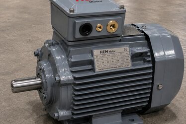
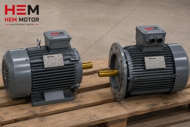
When an electric motor runs it does not only transmit torque from the shaft; it also continuously produces vibration on its body due to internal magnetic forces, imbalances and load reactions. The only thing that safely transfers this vibration to the ground without feeding it back is a rigid, correctly tightened bolt connection from the feet to the foundation. A loose or insufficient fixing causes the vibration to grow, cracks at the foot holes, and ultimately bearing and coupling damage. For this reason mechanical mounting must be taken as seriously as motor selection. We covered what the mounting code means (B3 foot-mounted, B5 flange-mounted) and how to state it when ordering in our IM mounting code reading guide; in this article our focus is directly on mechanical fixing, anchoring and tightening torque.
Correct fixing is also a prerequisite for meeting vibration acceptance values. When you compare the vibration value you measure in the field with the limits in our ISO 10816 vibration acceptance value article, remember that the measured value is affected not only by balance but also by mounting rigidity. If you want quiet, vibration-free operation, you should plan the mechanical base design before motor selection; you can find this as a complement in our noise and vibration focused motor selection content.
Selecting the Foot Bolt Size According to Frame Size
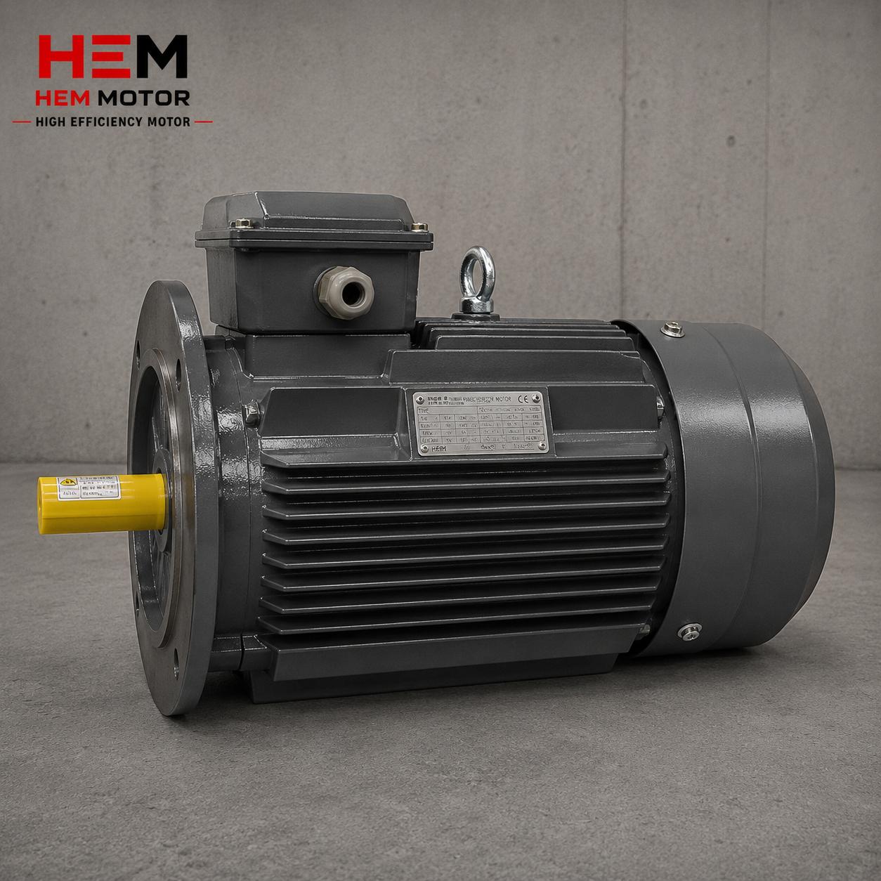
The diameter of the bolt that passes through the motor foot holes depends directly on the motor frame size (IEC frame). As the frame grows, the foot hole and therefore the bolt diameter increases. The table below gives approximate values commonly encountered in the industry; the exact bolt diameter must always be verified from the manufacturer dimension chart (foot hole diameter), because small differences may exist between manufacturers on the same frame.
Approximate foot bolt size – IEC frame relationship (for guidance):
- IEC 56–90 frame: approximately M8 – M10 foot bolt
- IEC 100–132 frame: approximately M12 foot bolt
- IEC 160–180 frame: approximately M16 foot bolt
- IEC 200–250 frame: approximately M20 foot bolt
- IEC 280–355 frame: approximately M24 foot bolt
You can find how to read the frame size together with the foot hole, shaft diameter and flange dimensions, and why it matters for ordering, in our cast iron motor frame IEC 56–355 weight and handling article, and the hole dimensions for flanged (FF/FT) connections in our cast iron motor flange type FF/FT hole dimensions content. Besides the foot bolt, the fixing on the shaft-coupling side that connects the motor to the machine should not be forgotten; we covered this in our flexible/rigid coupling selection and shaft alignment article.
Fixing to Concrete: Anchor Bolt, Chemical and Mechanical Dowel
If the motor sits directly on a concrete base, the foot bolt must be anchored to the concrete safely and in a vibration-resistant way. There are three common methods:
Cast-in (formwork) anchor bolt
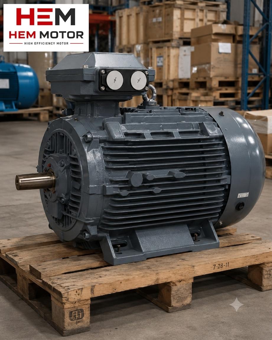
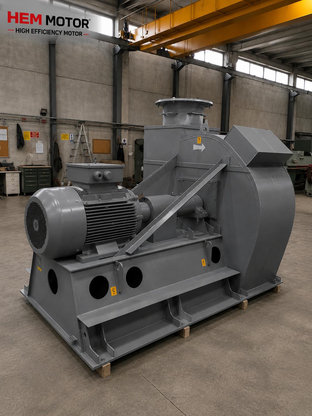
These are J or L shaped anchor bolts placed in the formwork while the concrete is poured. They provide the highest tensile and vibration resistance; they are preferred for heavy frame (IEC 250–355) cast iron motors and impact loads such as crushers, breakers and large fans. We explained why these motors require a rigid body under impact and vibration in our cast iron motor impact, rigidity and heavy load vibration article.
Chemical dowel (epoxy/resin anchor)
This is the method where a hole is drilled in cured concrete and a threaded rod is bonded by injecting resin. It provides high grip and vibration resistance; it is preferred when adding a motor to existing concrete later or when reinforcing a base.
Mechanical (expansion) dowel
This is a steel expansion dowel that anchors into the concrete as it is tightened. It is a practical solution for medium and small frame motors (IEC 56–160); however it is not as safe as a cast-in anchor or chemical dowel in heavily vibrating heavy applications. The concrete class, anchoring depth and edge distance must always be considered when selecting a dowel.
Whichever method is chosen, the base must have sufficient concrete mass to dampen vibration. General engineering practice recommends that a rotating machine base has a mass several times the machine weight; this reduces the risk of resonance and safely transfers vibration to the ground.
Approximate Tightening Torque Table for Class 8.8 Bolts
Selecting the foot bolt in the correct diameter alone is not enough; tightening the bolt to the correct torque is at least as critical. An under-tightened bolt loosens with vibration; an over-tightened bolt may strip its threads or crack the foot. The table below gives approximate tightening torque values commonly used for dry/lightly oiled class 8.8 bolts. These values are for guidance; the actual torque varies with bolt class, lubrication (friction) condition and manufacturer instruction, so base your work on the manufacturer torque table of the motor or fastener if available.
- M8 (8.8): approximately 25 Nm
- M10 (8.8): approximately 49 Nm
- M12 (8.8): approximately 85 Nm
- M16 (8.8): approximately 210 Nm
- M20 (8.8): approximately 410 Nm
- M24 (8.8): approximately 710 Nm
Apply the torque not by eye or by the feel of your arm but always with a calibrated torque wrench. If there are multiple foot bolts, tighten them in a cross (star) sequence and in stages (e.g. first 50% of the target, then 100%); this way the motor foot seats properly without being forced to one side. On an oiled bolt, because friction is reduced, the same torque produces higher preload; therefore it is important to match the lubrication condition with the manufacturer table.
Soft Foot, Foot Flatness and the Use of Shims
All four feet of the motor must rest equally and without gaps on the base before tightening. A foot remaining in the air or a gap between it and the base is called soft foot and bends the body when you tighten the bolt; this means internal stress, increased vibration and bearing damage. Soft foot is corrected by placing thin steel adjustment plates (shims) under the feet. Before tightening the bolts to final torque, check each foot one by one; you can detect the gap by loosening one foot and seeing whether the motor drops.
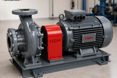
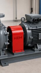
Foot flatness is also the basis of shaft alignment; coupling alignment done without correcting soft foot does not last. You can find the alignment method and tolerances in our coupling selection and shaft alignment article, and the fixing features in shaft-down applications in vertical (V1) mounting in our vertical mounting V1/V5 shaft-down selection content. To verify shaft diameter, key and coupling compatibility you can look at our cast iron motor shaft diameter, key and coupling article.
Safety Elements That Prevent Vibration and Loosening
One of the most common failures in rotating machine installation is bolts that loosen over time with vibration. Correct torque alone may not be enough; vibrating applications need an additional safety layer:
- Split (spring) washer: A basic measure for light/medium vibration; it helps on bolts under low load.
- Wedge-locking washer (Nord-Lock type): With its two-part, wedge-cammed surface it provides high resistance to loosening; preferred in heavily vibrating, impact applications.
- Nut locking (nylon insert / lock nut): A nylon insert nut or double nut (lock nut) prevents back-off.
- Thread locker (medium strength locking resin): On connections that should remain removable, it fills the thread gap and prevents loosening.
These measures prevent the vibration from gradually undoing the bolt, especially in variable load and impact drives. Distinguishing whether the source of vibration is mechanical or magnetic helps you choose the right measure; we examined this distinction in our asynchronous motor noise sources: magnetic and mechanical article. For safe lifting of the heavy motor during installation, apply the rules in our lifting eyebolt, handling and weight safety article.
Base/Frame Rigidity and Concrete Mass
No matter how correct the bolts and dowels are, if the frame or concrete base the motor sits on is not rigid enough, the vibration cannot be controlled. If a steel frame is used, the profile section must be selected to carry the motor weight and dynamic load, and reinforcements should be made between the feet to prevent twisting. A flexible frame amplifies vibration by going into resonance. On a concrete base, the mass and the connection to the ground are decisive; sufficient mass moves the natural frequency away from the operating speed and reduces the resonance risk. You can follow the check of the base and connection before commissioning, together with general first-start steps, in our motor commissioning and first start check article, and the mechanical and electrical pre-inspection at delivery in our incoming acceptance inspection: megger, rotation and vibration content.
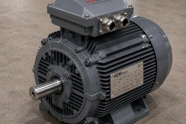
Relation with Terminal Box Orientation and Cable Side
When planning the mechanical fixing, the terminal box orientation and cable entry side of the motor must also be considered; otherwise the cable connection may be difficult or too close to the base edge after the motor is fixed. We explained stating the terminal box orientation in the order and selecting the correct side in our terminal box orientation and cable entry side selection article. For the correct selection on the cable lug and connection side, also look at our cable connection and cable lug selection content. For the right product range you can review our electric motors category and reach other related content from the electric motors blog category.
Frequently Asked Questions
Can I determine the foot bolt size definitively from the frame size?
The values in the table (e.g. approximately M12 for IEC 100–132) are a reliable starting point, but the exact size must always be verified from the foot hole diameter in the manufacturer dimension chart. There may be small differences between manufacturers on the same IEC frame; therefore evaluate the frame size and, if possible, the dimension table together when ordering. If you are replacing an existing motor, also measure the old foot holes.
Instead of tightening the bolts with torque, isn't firmly tightening by hand enough?
No. Tightening by hand or by estimation creates different preload from foot to foot; this means soft foot, body bending and vibration. Staged, cross-sequence tightening with a calibrated torque wrench to the value in the manufacturer table prevents both loosening and damage from over-tightening. The values we give for class 8.8 are for guidance; use the manufacturer torque if possible.
I will add a motor to existing concrete later, which fixing method should I choose?
For cured concrete, a chemical dowel (resin anchor) or a quality mechanical expansion dowel is generally used. In heavily vibrating, impact heavy applications the chemical dowel is safer. In any case the anchoring depth, edge distance and concrete class should be selected according to the dowel manufacturer technical data; make sure the base has sufficient mass.
Get a Quote
Consult our team to plan the right motor with the correct frame size, mounting type and suited to the application, together with the mechanical fixing requirements. When you tell us the load, vibration profile and base type of your application, we determine the most suitable motor with the right frame and mounting option together. You can reach us at +90 (532) 345 49 86 or send your quote request through our contact page. You can review our full range of electric motors from our homepage.
Purchasing and Installation Checklist
- Was the foot bolt diameter suitable for the frame size (e.g. ≈M12 for IEC 132) verified from the manufacturer chart?
- Was the concrete fixing method (cast-in anchor / chemical dowel / mechanical dowel) chosen according to the application?
- Are the base/frame rigidity and concrete mass sufficient to dampen vibration?
- Do all four feet seat without gaps; was soft foot corrected with shims?
- Was the correct torque (calibrated wrench, cross and staged) applied for the class 8.8 bolt?
- Was the lubrication/friction condition matched with the manufacturer torque table?
- Were anti-loosening elements (spring/Nord-Lock type washer, nut locking, locking resin) used?
- Was the shaft alignment done after soft foot was corrected?
- Are the terminal box orientation and cable side compatible with the mechanical fixing?