English
 Türkçe

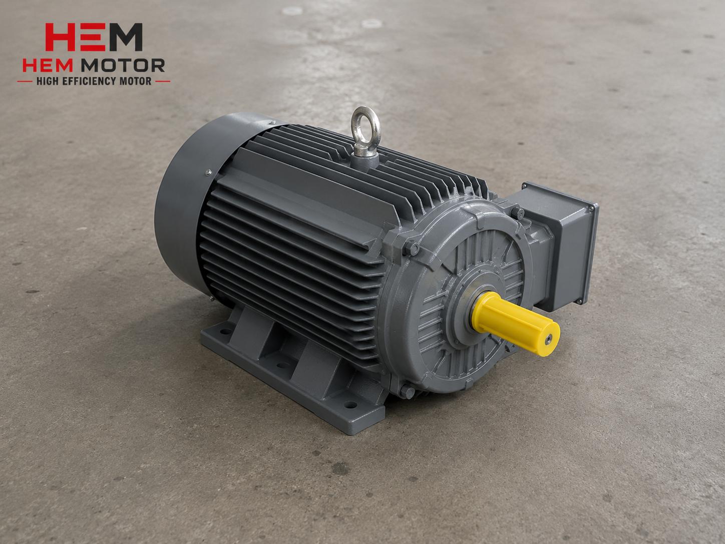
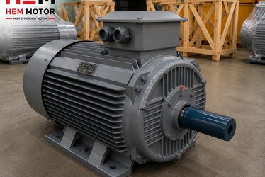
When you buy a cast iron bodied electric motor, the detail most often overlooked, yet the one that decides the fate of the installation day, is the motor shaft diameter. A wrong shaft diameter, an incompatible key size, or a poorly balanced coupling can single-handedly affect the power, efficiency, and lifespan of the motor you purchased. As HEM Motor, with our identity as both manufacturer and supplier, one of the most common ordering mistakes we encounter is motors whose frame size was chosen correctly but whose shaft end, key, and coupling compatibility were never checked. This guide was prepared to help you correctly match shaft diameter, key, and coupling when buying a cast iron motor, so you can build a working mechanical system without disassembly headaches when it arrives on site.
The Relationship Between IEC Frame Size and Shaft Diameter
In electric motors the shaft diameter is not a random value; it is determined by the frame size according to IEC standards. Once you know a motor frame size, you can largely predict the shaft end diameter. This is the direct continuation of frame size and power matching in cast iron bodied motors: the frame size first sets the power, then the shaft diameter.
Commonly used IEC frame size to shaft diameter matches are as follows:
- 63 frame: Ø11 mm shaft diameter
- 71 frame: Ø14 mm shaft diameter
- 80 frame: Ø19 mm shaft diameter
- 90 frame: Ø24 mm shaft diameter
- 100-112 frame: Ø28 mm shaft diameter
- 132 frame: Ø38 mm shaft diameter
- 160 frame: Ø42 mm shaft diameter
- 180 frame: Ø48 mm shaft diameter
- 200 frame: Ø55 mm shaft diameter
- 225 frame: Ø60 mm shaft diameter
- 250 frame: Ø65 mm shaft diameter
- 280 frame: Ø75 mm shaft diameter
- 315 frame: Ø80 mm shaft diameter
- 355 frame: Ø100 mm shaft diameter
In the Turkish market, especially at high powers (315 kW and 355 kW, 1500 rpm), the most common combination is a 355 frame and Ø100 mm shaft diameter. Because our cast iron bodied motors are produced in a wide range from 63 frame to 355L frame (including 315HT), we can meet the power and shaft diameter combination your machine needs directly from stock or with fast production. The shaft diameter should be chosen not only to carry the power but also to match the bore diameter of the coupling or pulley it will connect to.
Key Size: The Critical Part That Transmits Torque
The key on the shaft end transmits the torque the motor produces to the coupling, pulley, or gear reducer input. The keyway and key size are also determined in proportion to the shaft diameter per IEC. A wrong key renders even the strongest motor useless, because torque transmission passes through the key.
Typical Key Sizes by Shaft Diameter
Common DIN 6885 / IEC based key width x height values:
- Ø11 mm shaft → 4 x 4 mm key
- Ø14 mm shaft → 5 x 5 mm key
- Ø19 mm shaft → 6 x 6 mm key
- Ø24 mm shaft → 8 x 7 mm key
- Ø28 mm shaft → 8 x 7 mm key
- Ø38 mm shaft → 10 x 8 mm key
- Ø42 mm shaft → 12 x 8 mm key
- Ø48 mm shaft → 14 x 9 mm key
- Ø55 mm shaft → 16 x 10 mm key
- Ø60 mm shaft → 18 x 11 mm key
- Ø100 mm shaft → 28 x 16 mm key
When you specify the shaft diameter in an order, the key size comes automatically per the catalog; however, if your machine requires a special key height (for example a reduced or raised key), you must state it during ordering. Otherwise the key on the motor arriving on site may not seat into the channel of your existing pulley bore. In our motor shaft diameter and key dimensions guide we detailed all dimensions to check before ordering.
Coupling and Pulley Balance: The Key to Vibration-Free Operation
The third pillar of mechanical matching is the element fitted to the shaft end: a coupling (direct drive connection) or a belt-pulley. The high mechanical strength and low vibration advantage of the cast iron body only becomes meaningful with a properly balanced coupling or pulley. An unbalanced coupling continuously imposes radial load on the motor bearings and significantly shortens bearing and seat life.
Coupled (Direct) Connection
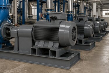
In axially aligned applications such as pumps, compressors, or gear reducers, the motor is usually coupled with a flexible coupling. In this case the shaft diameter must exactly match the coupling bore, and axial alignment must be done with a laser or dial gauge. The most preferred mounting types for coupled connections are B3 foot-mounted and B35 (foot + large flange) motors. The B3 mounting type offers a shaft and key structure suitable for belt-pulley, coupling, and gear reducer connections.
Pulley (Belt) Connection
In applications such as crushers, fans, and mills, power is often transmitted by V-belt. Here, as much as pulley balance, the radial load on the shaft end is important; an over-tensioned belt fatigues the shaft. The rigidity of the cast iron body keeps vibration low in belt-driven applications. To choose the correct mounting type, you can review our electric motor mounting types page and evaluate the B3/B5/B35 options according to your application.
Considering Mounting Type and Shaft-Coupling Compatibility Together
Even if the shaft diameter and key are correct, if the mounting type does not suit your machine the motor is useless on site. Therefore mechanical matching must always be evaluated together with the mounting type:
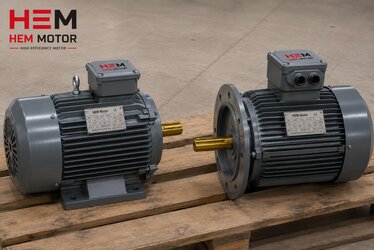
- B5 (large flange, footless): In the 63-355 frame range, bolted directly to a gear reducer or pump body via the large flange on the front cover. In our high-efficiency electric motors the B5 flange is one of the standard options.
- B14 (small flange, footless): In the 56-160L frame range, for small-flange compact applications.
- B35 (B3 + B5): Connects both to the chassis by feet and to the machine by the large flange; distributes shaft-coupling load in heavy and vibrating applications.
B5 and B14 flange dimensions differ; fitting one in place of the other is usually not possible. For the correct flange choice we recommend reading our B5 vs B14 connection type selection guide. If you wonder whether shaft and foot dimensions stay the same when switching to IE4 efficiency class, our mechanical compatibility in switching to IE4 motors article answers this directly.
Shaft Tolerance, Double Shaft and Special Shaft Requests
As much as the shaft diameter, the shaft tolerance determines how the coupling or pulley seats. Standard electric motor shafts are usually machined to k6 tolerance; this ensures the coupling bore seats with an interference fit and prevents slipping during rotation. If your existing pulley has an H7 bore, you obtain a slight interference fit with a k6 shaft. Verifying both diameter and tolerance before ordering eliminates the problem of forced fitting or clearance on site.
Some applications require non-standard solutions at the shaft end:
- Double-ended shaft: In applications requiring drive from both front and rear ends (for example a double-sided fan or an encoder connection), a double shaft can be requested. This must be specially stated at the ordering stage.
- Special shaft length/diameter: For exact fit to an existing machine, the shaft may need to be machined to a non-standard length or diameter. Such special shaft requests can be met during production in cast iron bodied motors.
- Shaft end thread (center hole/screw): For axial fixing of the coupling or pulley there is a center hole and threaded connection at the shaft end; this fixing is essential for heavy pulleys.
If you are replacing your existing motor one-to-one, measuring the old motor shaft diameter, length, key size, and shaft end thread and sending them to us is the safest way. In our replacing an old brand motor one-to-one article we explained all the dimensional points to watch in equivalent motor selection. To prevent the wrong motor arriving, you can also use our nameplate matching checklist.
Pre-Order Mechanical Matching Checklist
Before ordering a cast iron motor, clarifying the following four mechanical data points guarantees the right motor arrives on site:
- Frame size: From 63 to 355L; sets the power and shaft diameter together.
- Shaft diameter and tolerance: For example Ø38 mm k6 or Ø100 mm k6; must exactly match the coupling/pulley bore.
- Key size: Standard per shaft diameter; specify if a special height is required.
- Mounting type: B3, B5, B14, B35, or B34; determines how it connects to your machine.
When you communicate these four data points correctly, the motor works on arrival without additional machining or adaptation. To apply the same discipline on the power and speed side, our information to provide when requesting a quote guide is a complementary resource.
The Cast Iron Body Advantage in Mechanical Matching
The cast iron body offers a more rigid structure than aluminum. This rigidity ensures shaft alignment does not deteriorate during use and that coupling/pulley balance is preserved. Under high torque and impact load, an aluminum body may flex, while a cast iron body keeps its form. If you cannot decide between cast iron and aluminum, our cast iron vs aluminum body comparison helps you choose according to environmental conditions. Our IE4 cast iron bodied motors are offered in the 0.25 kW - 355 kW range with IP55 protection and class F insulation.
Frequently Asked Questions
What is the shaft diameter of a 355 frame motor?
According to IEC standards, the shaft end diameter of a 355 frame motor is Ø100 mm. In Turkiye, for 315 kW and 355 kW, 1500 rpm motors the most common combination is a 355 frame and Ø100 mm shaft. We recommend confirming before ordering that the bore diameter of your existing coupling or pulley matches this value; if there is a mismatch, choosing the correct hub is healthier than machining the shaft.
Do I need to specify the key size separately?
In standard applications no; when you specify the shaft diameter, the key size comes as standard per the IEC/DIN 6885 catalog (for example 28 x 16 mm key for a Ø100 mm shaft). However, if your existing pulley bore is machined with a special key height or a double-keyed shaft is required, you must inform us at the quotation stage.
Does coupling balance affect the motor warranty?
An unbalanced coupling or pulley can cause early failure by imposing excessive radial load on the bearings, and this is assessed as usage-related damage. If you make an aligned installation with a properly balanced coupling matched to the shaft diameter, the motor lasts longer and your warranty process runs smoothly. An alignment check before commissioning is essential.
Get a Quote
Let us evaluate your machine frame size, shaft diameter, key size, and mounting type together and quickly supply the right cast iron motor. By sharing your current motor nameplate information and connection details, you can get an exact-equivalent quote. Call us at +90 (532) 345 49 86 or reach us through our contact page; let us check shaft and coupling compatibility for you and ship the right motor to site.