English
 Türkçe
Lifting a cast-iron motor is not as harmless a task as bolting on a cable or reading the nameplate. When you raise a cast-iron body that can weigh from a few hundred kilograms to well over a tonne with a crane, forklift or chain hoist, the entire load gathers at a single point: the lifting eyebolt. An eyebolt that is wrongly selected, wrongly installed or pulled at the wrong angle can cause the motor to fall and seriously injure anyone standing beneath it. In this article we cover, in engineering terms but with the clarity a buyer and field installer needs, the lifting eyebolt (ring bolt) on cast-iron motors, the concept of WLL (Working Load Limit) stamped on it, why angled pulling is so dangerous, the use of multiple eyebolts, and the lifting points cast into the iron body. The goal is single: to lift the heavy cast-iron body safely every single time.
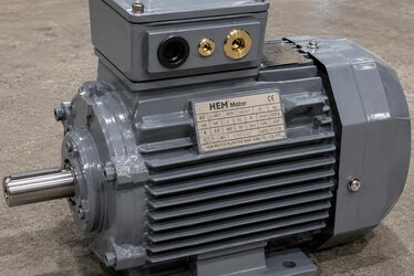
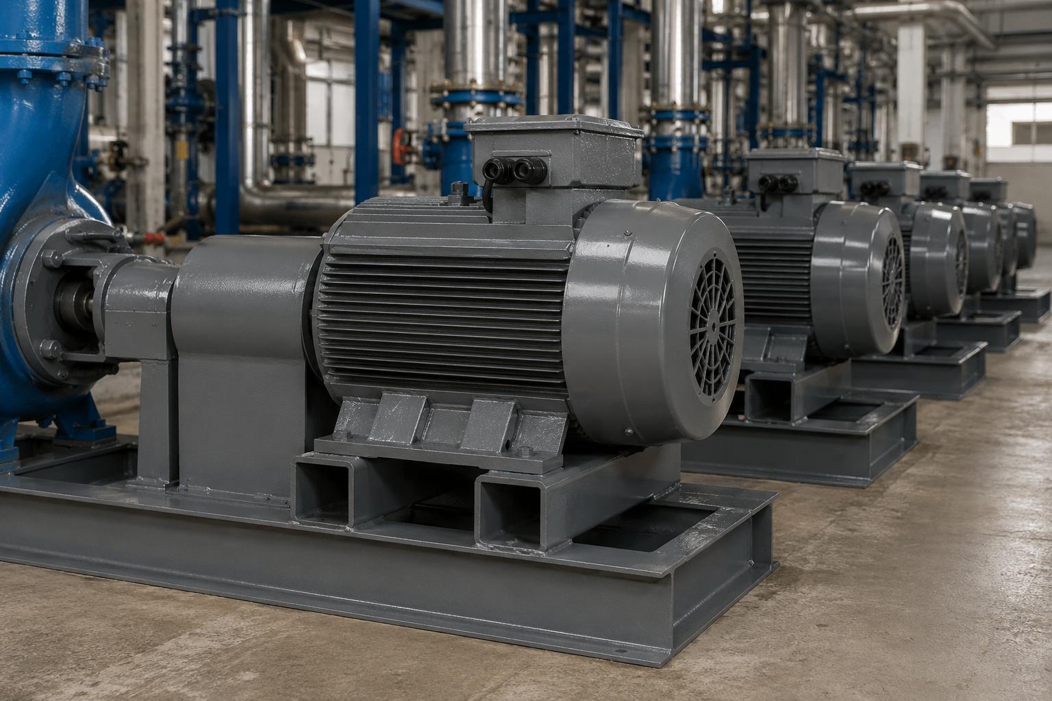
At HEM Motor we deliver cast-iron body motors from stock, and we know that most buyers unload and install the motor with their own crane on site after receiving it. For this reason, the correct class, correct size and correct use of the eyebolt is not merely a quality detail but a direct occupational safety issue.
What Is a Lifting Eyebolt (Ring Bolt)?
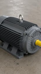
A lifting eyebolt is a forged steel lifting element with a ring (eye) on top that is screwed into a threaded hole in the motor body. The most common standard is DIN 580. DIN 580 eyebolts are produced in metric thread sizes from M8 to M100; each size has a nominal load it can carry in vertical (axial) pull. On cast-iron motors the eyebolt is fitted into a threaded point cast or machined into the body, located to balance the centre of gravity of the heaviest parts of the motor (stator pack, cast body, shaft).
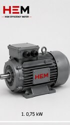
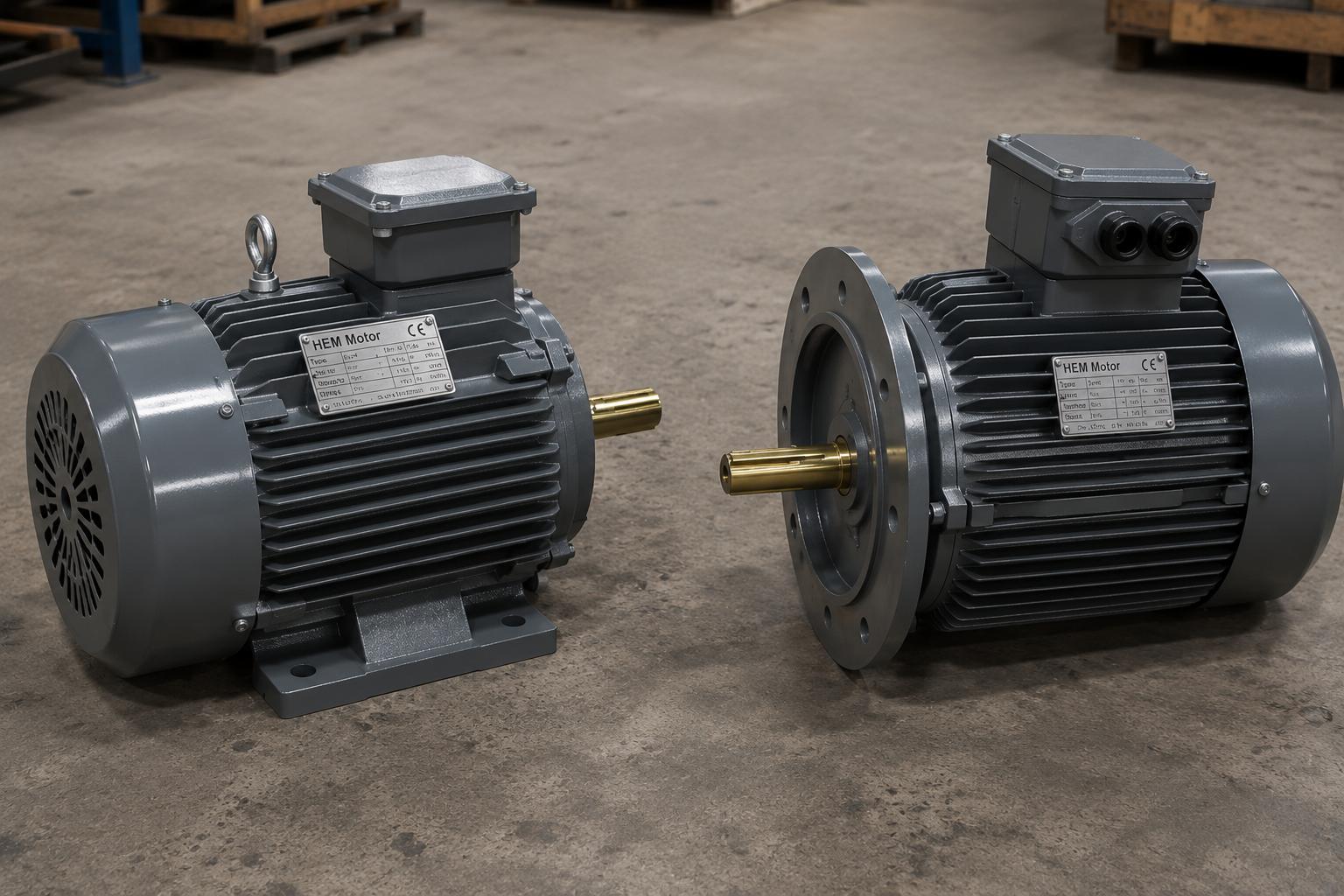
The critical point here is this: the eyebolt must be selected to lift the entire weight of the motor, not just the body shell. Total motor mass varies significantly with power rating and frame size. Since a cast-iron body is far heavier than aluminium, the lifting load is considerably higher than for an aluminium motor of the same power. We covered the effect of frame choice on weight in detail in our article on cast iron versus aluminium frame; any lifting plan must account for this difference.
What Is WLL (Working Load Limit) and Why Is It Lower Than the Breaking Load?
WLL (Working Load Limit) is the maximum load a lifting element can safely carry under normal working conditions. WLL is not the load at which the element breaks; it is found by applying a safety factor (typically 4:1 or 5:1) to the breaking load. So an eyebolt with a WLL of 1000 kg may break in the lab at around 4000-5000 kg; the difference is the safety margin and must never be treated as "usable reserve".
Another critical fact about DIN 580 eyebolts: WLL decreases with the pulling angle. When the eyebolt is pulled straight (axial, 0°) it carries its nominal value. As the pulling angle increases, that is as the sling legs approach horizontal, the actual force on the eyebolt multiplies and the permitted load drops rapidly.
Eyebolt Size, Class and WLL Table
The table below summarises the approximate vertical-pull WLL values of DIN 580 forged ring bolts by metric size, plus the remaining capacity in angled pull. Values are based on typical catalogues; the eyebolt manufacturer's own documentation must be used for final selection.
| Thread (Metric) | WLL Vertical (0°) | WLL ~45° Single Leg | Typical Motor Range |
|---|---|---|---|
| M8 | ~140 kg | ~90 kg | Small frame / cover |
| M12 | ~340 kg | ~200 kg | Small-medium motor |
| M16 | ~700 kg | ~410 kg | Medium frame motor |
| M20 | ~1200 kg | ~700 kg | Large frame motor |
| M24 | ~1800 kg | ~1050 kg | Heavy cast body |
| M30 | ~3200 kg | ~1850 kg | Very heavy motor |
The critical message from the table: when pulled at a 45° angle, the safe capacity of a single eyebolt drops by roughly 40% compared with vertical pull. This is why the pulling angle must always be kept as close to vertical as possible.
The Risk of Angled Pull: Why Does the Force Multiply?
When lifting from two points, the larger the angle between the sling legs, the greater the force on each leg. In a 0° (vertical) pull each leg carries half the load, while at a 90° angle (legs nearly horizontal) the force on each leg theoretically approaches infinity. The practical rule: the sling angle should never exceed 60° and ideally be kept below 45°. Angled pull also subjects standard DIN 580 eyebolts to side loading, and their side-load strength is low. For applications with side loading, swivel hoist rings should be preferred; these carry full WLL in any direction.
- Vertical pull (0°): The eyebolt carries its nominal WLL, the safest method.
- 45° pull: Safe capacity drops to ~70-75%; the standard acceptable limit.
- 60° pull: Capacity drops to ~50%; careful planning required.
- Above 60°: Dangerous; must not be done with standard DIN 580.
Multiple Eyebolts and Lifting Points on the Cast Body
Large cast-iron motors have two or more lifting points instead of a single eyebolt. These points are usually lugs cast integrally into the body or threaded sockets machined into it. When using multiple eyebolts, never forget two basic rules:
- The load may not distribute evenly between the eyebolts. In a two-point lift even small differences in chain/sling lengths can load most of the weight onto a single eyebolt. Each eyebolt must therefore be selected to carry a significant portion of the total load on its own.
- Use only the eyebolts on the motor body. The terminal box, fan cowl, cooling fan, bearing cap or gearbox flange are never lifting points. These parts carry no structural load and will break.
Lifting lugs integrated into the cast body are more reliable than screwed eyebolts because there is no risk of thread loosening or incorrect torque. Even so, before every lift they should be checked for cracks, corrosion or impact marks on the surface. On motors operating in the open, corrosion can also weaken the lifting point; we examined this in our article on open-field corrosion protection.
Correct Installation and Torque of the Eyebolt
A DIN 580 screwed eyebolt must be tightened by hand until the full thread is seated, with the ring plane oriented parallel to the pulling direction. If the eyebolt is loaded with the thread only half engaged, the thread strips and the eyebolt breaks. The thread must be clean, undamaged and of the correct size. To understand the relationship between the motor frame size and the shaft/thread dimensions correctly, our article on frame size and power matching is helpful.
For general lifting and pre-installation checks, our article on motor lifting eyebolt, weight and safe handling completes this topic for all motor types. For correct replacement and frame size selection, our article on shaft diameter and frame table (IEC 56-355) also helps you estimate the eyebolt thread size by frame size.
Centre of Gravity and Lifting Balance
On cast-iron motors the centre of gravity is not always at the geometric middle of the body. Options such as the terminal box, an additional gearbox flange, a forced-cooling fan or a brake unit shift the centre of gravity. When lifting with a single eyebolt the motor turns or swings until the centre of gravity comes directly under the eyebolt. If this swing is uncontrolled it both creates a hazard for personnel and damages the shaft, coupling or connection elements. Therefore:
- Anticipate which way the motor will turn before lifting; keep the rotation under control with a tag line.
- Use the lifting point specified by the factory where possible; these points are located with the centre of gravity in mind.
- On complete units with a gearbox or pump fitted, the motor's own lifting point is not enough to balance the whole unit; make a separate lifting plan for the complete unit.
On heavy cast-iron motors the bearing position must also not take impact during lifting; sudden jolts can disturb the bearing clearance and alignment. Our article on bearing and bearing life on cast-iron motors contains complementary information.
Eyebolt Material Class and Marking
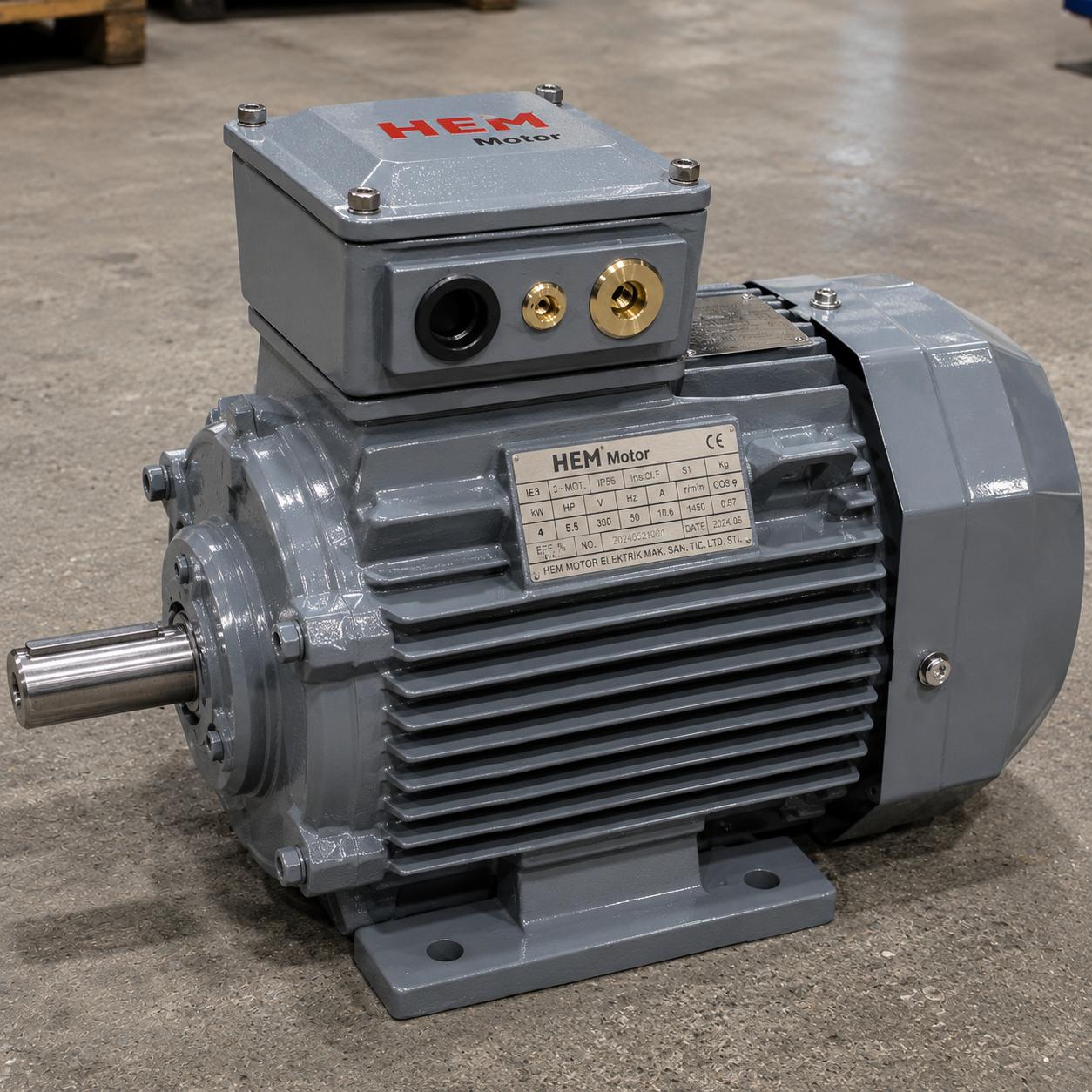
DIN 580 eyebolts are usually produced from C15 / S235 class forged steel and carry the manufacturer's mark, the size and in some cases the load class. An eyebolt that is unmarked, rusty, has a bruised thread or a deformed ring must not be used. Eyebolts are reusable lifting elements; they must be visually inspected before each use, and deformed ones must be immediately taken out of service. Temperature also matters: standard steel eyebolts lose WLL in high-temperature applications; above 200°C the manufacturer's data is essential.
In short, the safe lifting of a cast-iron motor rests on three pillars: a correctly sized and sound eyebolt, a pulling angle close to vertical and the use of structural lifting points only. When these three are ensured, even a cast body of over a tonne can be raised and installed safely.
On-Site Pre-Lift Checklist
Before actually raising a cast-iron motor, a quick checklist on site prevents the majority of accidents. This list is not merely a formality but a practical discipline that keeps the heavy cast body under control. Having the lifting crew follow the same steps each time avoids habit errors and ensures consistency, especially in plants where motors of different sizes are handled one after another.
- Weight confirmation: Confirm the real weight of the motor from the nameplate or catalogue; do not trust a guess.
- Eyebolt inspection: Check the size, marking and physical condition (cracks, rust, bruised thread, deformed ring) of the eyebolt to be used.
- Thread check: Make sure the threaded hole in the body is clean, undamaged and compatible with the eyebolt.
- Sling and crane capacity: Verify that the WLL of the sling, chain and crane comfortably covers the motor weight.
- Angle plan: Set up a sling arrangement where the pulling angle is close to vertical; use a lifting beam to correct the angle if needed.
- No personnel underneath: No one must be under the motor or in the possible fall line while the load is in the air.
Frequently Asked Questions
What should I do if the WLL on the DIN 580 eyebolt is less than the motor weight?
Never use that eyebolt under any circumstances. If the WLL is below the motor weight, either select a larger eyebolt (bigger thread) or switch to multi-point lifting. WLL is a value with the safety factor already applied; an "I will exceed it a little" approach means a risk of breakage. Moreover, the real load increases further in angled pull, so always choose an eyebolt that allows pulling close to vertical and leaves a margin above the WLL.
Can I lift the motor by the terminal box or the fan cowl?
Absolutely not. The terminal box, fan cowl, bearing cap and similar parts are not designed for structural lifting; they break under load and cause the motor to fall. Only lifting lugs cast into the body or certified eyebolts fitted into threaded points on the body should be used.
In a twin-eyebolt lift, should I size each eyebolt for half the load?
No, to be safer, size each eyebolt to carry a significant portion of the total load on its own. Differences in sling lengths and angle cause the load to distribute unevenly; in practice one eyebolt may carry more than expected. Keeping the sling angle narrow (close to vertical) also reduces the load on both eyebolts.
So that you can receive your cast-iron body motors together with the correct lifting point, correct frame size and complete accessory information, HEM Motor offers fast supply from stock. For the right frame, lifting point and installation details for your application, get in touch with us and let our team prepare a quotation with the most accurate solution.