English
 Türkçe
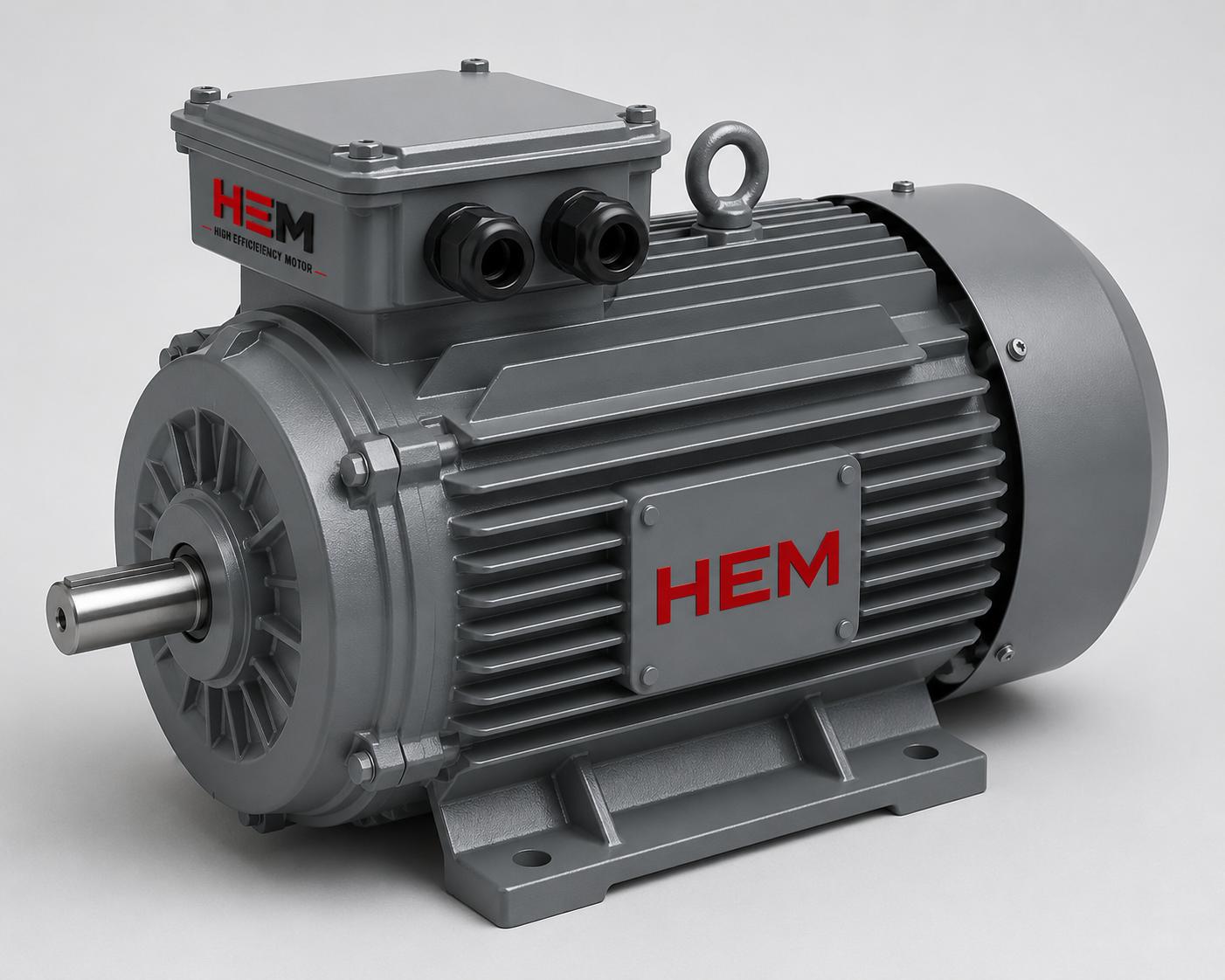
One of the most critical factors that determine the lifespan and quiet operation of a cast iron electric motor is the shaft bearing arrangement. A motor rotor turns on two bearings, one at the front and one at the rear; however, the job of these two bearings is not the same. One locates the rotor axially and holds it in position, while the other allows the heat-expanded shaft to grow freely. If this distinction is not made, the shaft expands as the motor heats up, the bearings are pushed toward each other and axial preload builds up inside them; the result is premature bearing failure, overheating and vibration. In this article we examine the locating bearing and the floating bearing arrangement, why axial clearance is provided, and how to select the right cast iron motor for your application, all from a procurement and supply point of view.
Why Do Locating and Floating Bearings Exist?
The shaft of an electric motor is a steel part and it grows in length when it reaches operating temperature. In a typical motor, when the shaft temperature rises from ambient to operating temperature, a noticeable axial expansion occurs depending on the shaft length. If both bearings were locked axially to the housing, this expansion would squeeze the bearings, apply unbearable pressure on the balls or rollers and break the oil film, causing metal-to-metal contact. For exactly this reason, the classic solution is adopted in cast iron motors: a locating bearing at one end and a floating bearing at the other.
The locating bearing carries both the radial load and the axial load in both directions; it keeps the rotor in the correct position within the air gap. Its inner ring is fixed axially to the shaft and its outer ring to the bearing housing, usually locked on both sides by a cover or a circlip. The floating bearing, on the other hand, carries only the radial load and its outer ring can slide slightly in the axial direction within the bearing housing. When the shaft expands, the bearing on the floating side slides a few tenths of a millimetre inside its housing and absorbs the expansion. In this way the axial preload is kept under control and the bearing reaches its design life.
Which End Is Locating and Which Is Floating?
The general rule is that the locating bearing is at the drive (D) end, that is, the front side where the coupling or pulley is connected, because the axial load mostly comes from here and the rotor position must be set relative to the output shaft. The floating bearing is placed at the rear (N) end, the fan side. However, this rule is not absolute: in vertically mounted motors, in applications with large impeller or coupling thrust, or in special designs, the arrangement may change. When selecting the right cast iron motor, informing the manufacturer of the application axial load direction and mounting position ensures that the factory supplies the correct bearing arrangement.
- Drive (D) end: Usually the locating bearing; the coupling, pulley or gearbox is connected here.
- Rear (N) end: Usually the floating bearing; the cooling fan is here and the axial expansion is absorbed at this end.
- Vertical mounting (V1/V3): The axial load combines with gravity; the direction and size of the locating bearing are chosen accordingly.
- Large frames: On frame 280 and above, a roller bearing at the drive end and a ball bearing at the rear may be preferred.
Axial Clearance: Why and How Much?
For the floating bearing to perform its function, an axial clearance is left inside the housing within which it can move. This clearance must be slightly more than the distance the shaft can expand when the motor reaches its highest operating temperature. If the clearance is insufficient, when the shaft is fully expanded the floating bearing hits the end of the housing and is no longer free; in this case the axial preload rises dangerously. If the clearance is more than necessary, the rotor stays axially loose when cold and, especially in vertical mounting, unwanted noise and axial oscillation may occur.
In ball bearings the floating action is usually provided by the outer ring sliding within the housing. In higher powers a cylindrical roller bearing (NU type) is used; the inner and outer rings of these bearings can be separated and the rollers can slide axially on the outer ring, so even very large expansions are absorbed smoothly. The high mechanical rigidity of the cast iron housing ensures that these bearing tolerances are maintained throughout operation; because its thermal expansion is lower than aluminium, the bearing housing dimensions stay more stable.
Axial Preload and the Wave Washer
On small and medium frames, a wave washer (spring washer) that applies a light axial force to the outer ring of the floating bearing is used so that the rotor does not stay loose even when cold. This spring applies a continuous but small preload to the bearing, ensuring the balls slide within the housing and run quietly; it also compresses to absorb excess load when the shaft expands. A correctly designed spring preload minimises bearing noise and vibration in both cold and hot operation. These details are standardised by the factory according to frame size; therefore a correctly bearing-arranged motor supplied from stock is far more reliable than a motor stripped and adjusted in the field.
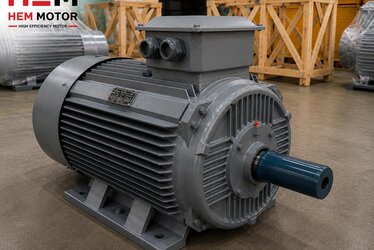
The Contribution of the Cast Iron Body to Bearing Performance
The dimensional stability of the bearing housing is a direct determinant of bearing life. Thanks to its high modulus of elasticity and low coefficient of thermal expansion, the cast iron body keeps the bearing housing round and on-dimension even at operating temperature. Under heavy shock loads, belt tension or large coupling masses, the body does not flex; this ensures the bearing outer ring seats correctly in the housing and the floating side slides without jamming. Cast iron body motors are therefore preferred over aluminium in crusher, grinder, large fan and heavy industrial applications.
- High rigidity: the housing does not become oval under belt tension and radial load.
- Low thermal expansion: the bearing clearance stays at the design value when hot.
- Vibration damping: the mass of cast iron absorbs vibration and extends bearing life.
- IP55 protection and class F insulation for safe operation in dusty, humid environments.
For a correctly bearing-arranged cast iron motor across a wide power range you can request a quote through our cast iron body electric motors range and current elektrik motoru fiyatları.
Preventing Bearing Failure: A Purchasing Checklist
Most problems related to shaft bearing arrangement stem from wrong or missing information given at the time of order. For correct supply, clarify the following points with the manufacturer:
- Mounting position: Horizontal (B3/B5) or vertical (V1/V3)? The axial load direction depends on this.
- Load type: Coupling (axial thrust) or belt-pulley (radial load)? A belt application requires a reinforced bearing.
- Bearing clearance class: C3 clearance is usually recommended for drive-fed, hot or continuous high-speed operation.
- Re-greasing: On large frames, a grease nipple and a re-greasable bearing can be requested.
- Operating temperature and environment: High ambient temperature increases axial expansion; the bearing arrangement is designed accordingly.
Once these details are clarified, the factory applies the correct bearing arrangement, the correct bearing type and the correct axial clearance from the very beginning. For bearing clearance selection in drive-fed and hot environments our C3 bearing clearance selection guide, and for radial load limits our shaft radial and axial load limit content provide complementary information.
Correct Supply Requires Manufacturer Assurance
Shaft bearing arrangement is an internal design decision that cannot be evaluated by eye before installation; the buyer can only verify it once the motor runs quietly, cool and vibration-free under field conditions. For this reason the bearing arrangement is one of the biggest risk areas in cheap second-hand or uncertified motors. A motor produced with the correct locating/floating bearing arrangement, the correct axial clearance and a suitable wave washer preload, that has passed the routine test and can be supplied quickly from stock, is the most economical solution in the long run. In a cast iron motor supplied with manufacturer assurance the bearing parameters are documented; in case of failure the warranty scope is clear and the supply of a spare motor is faster.
Across a wide power range, ready with B3/B5/B35 mounting options and correctly bearing-arranged general purpose industrial motors are kept in stock; by providing the axial load and mounting information of your project you can obtain a quote and lead time with the correct bearing arrangement.
Frequently Asked Questions
Why is the locating bearing at the drive (front) end?
Because the axial thrust load usually comes from the coupling or pulley, that is, from the drive end, and the rotor position must be set relative to the output shaft. The locating bearing locks this end axially and keeps the rotor in the correct position in the air gap; the floating bearing at the rear absorbs shaft expansion. In vertical mounting or applications with special thrust load this arrangement may change, so the mounting and load information must be provided before ordering.
What happens if the axial clearance is insufficient?
When the motor heats up the shaft expands; the floating bearing hits the end of the housing and can no longer slide freely. In this case the axial preload between the two bearings rises dangerously, the oil film breaks down, the bearing overheats and fails far below its design life. In a correctly designed motor the clearance is more than the expansion at the highest operating temperature; this is standardised by the factory according to frame size.
Why is a cast iron body better than aluminium for bearing performance?
Cast iron has a high modulus of elasticity and low thermal expansion. As a result the bearing housing does not become oval under belt tension or shock load and keeps its dimension at operating temperature; the floating bearing slides without jamming. The mass of cast iron also damps vibration. For these reasons cast iron body motors are preferred in heavy duty, crusher, large fan and continuous load applications.