English
 Türkçe
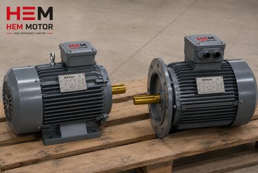
When an electric motor arrives on site, one of the first things to do is to lower, handle and place it safely at the installation point. This seemingly simple step is actually a critical moment for both worker safety and the motor's health. The lifting eyebolt (lifting lug) on the motor is designed only to lift the motor's own weight; it must not be used for the extra load of a pump, gearbox, pulley or any other attached equipment. Incorrect lifting can cause the eyebolt to break, the motor to fall, and lead both to serious injury and to hidden damage to the motor. In this article we explain the correct use of the lifting eyebolt, how motor weight rises with frame size, how to choose the sling and crane angle, and the pre-mounting checklist. As HEM Motor, we deliver motors safely to site and provide guidance on correct handling.
A motor falling or being lifted incorrectly often causes damage that is not immediately visible but shortens the motor's life: shaft bending, bearing damage, frame cracking or winding loosening. These damages appear as vibration, heating and premature failure once the motor starts running. This is why correct lifting and handling is an invisible but decisive part of installation.
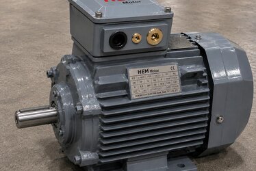
What Is the Lifting Eyebolt Designed For?
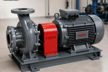
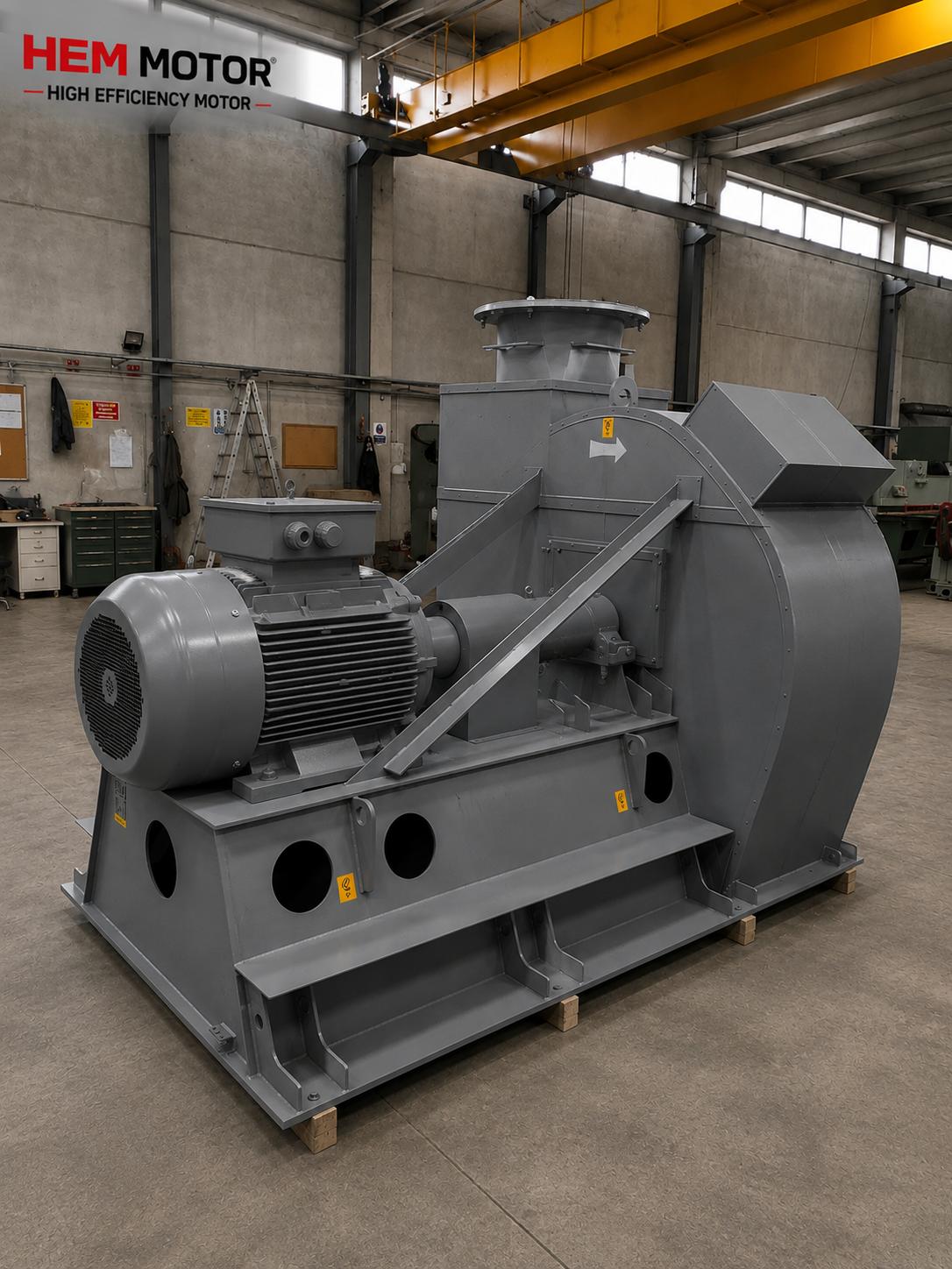
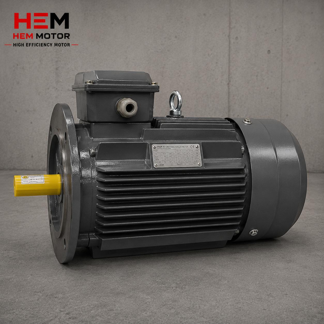
The lifting eyebolt screwed into the motor frame is sized only to safely lift the motor's own weight. The manufacturer designs the eyebolt according to the motor's net weight and a certain safety factor. This is why the eyebolt is enough to lift the motor's weight but is not designed to carry the extra load of a pump, gearbox or pulley attached to the motor afterwards. If the motor is lifted while coupled to a pump or gearbox, the total load on the eyebolt exceeds the design limit and the eyebolt can break.
For this reason the basic rule is: the lifting eyebolt is used only to lift the motor. If the motor is attached to other equipment, a separate lifting arrangement planned according to the center of gravity and suitable lifting points of that combined system is required. Also, on single-eyebolt motors, for balanced lifting it is important that the eyebolt is above the motor's center of gravity; otherwise the motor swings unevenly when lifted.
Check Before Using the Eyebolt
- Soundness of the eyebolt: Make sure the eyebolt seats fully into the frame and is not loose or cracked.
- Screwing depth: The eyebolt must be screwed fully and properly into the thread in the frame; an incompletely screwed eyebolt can break under load.
- Load direction: Eyebolts are usually designed for vertical loads; forces coming from a side angle overstress the eyebolt.
- No extra load: If the motor is attached to a pump, gearbox or pulley, the motor's eyebolt must not be used to lift this combined load.
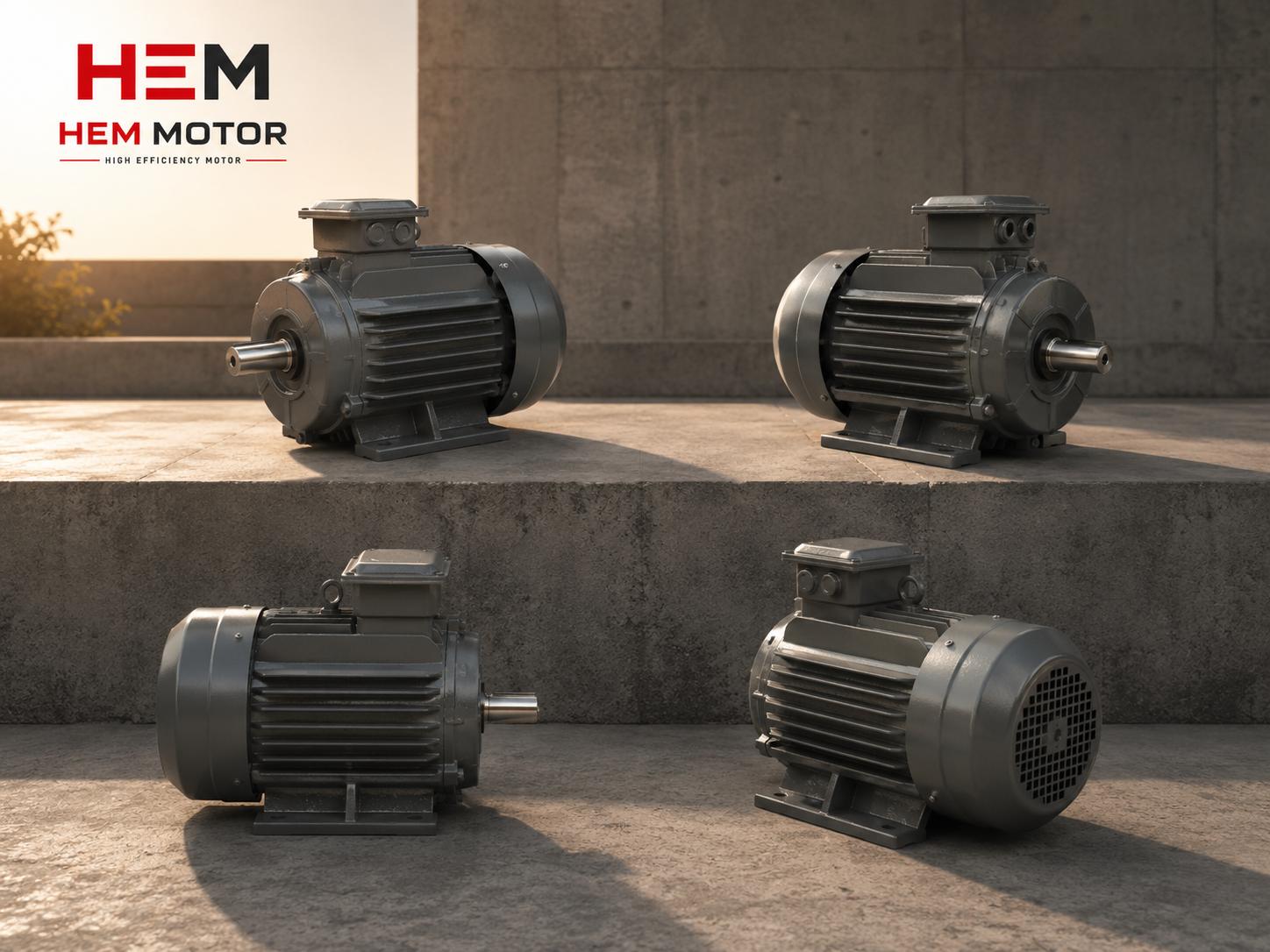
How Does Motor Weight Rise with Frame Size?
The weight of electric motors rises rapidly as power and frame size grow. A motor weighing a few tens of kilograms at low power can reach hundreds of kilograms at medium power and tons at high power. The reason for this rise is that as power increases, the amount of winding, the iron core and the frame volume grow. Moreover, cast iron frame motors are heavier than their aluminum frame equivalents, because cast iron is both a denser material and has a thicker structure for heavy duty.
This is why it is essential to know a motor's weight before lifting it. The weight information is given on the motor's nameplate or in the catalog. Sling capacity, crane capacity and the lifting arrangement must be chosen according to this weight. Assessing weight by "eyeball estimate" can lead to using a sling or crane of insufficient capacity and to a serious accident. For the relationship between frame size and weight, resources covering the structure of cast iron frame motors can offer guidance.
Why Are the Sling and Crane Angle Important?
When lifting a motor, the angle of the sling directly affects the real load on the eyebolt. When lifting from two points, as the angle between the slings increases, the force on each sling and eyebolt increases. When the slings are vertical (close to upright), the load is distributed evenly between the two points and each eyebolt receives a force equal to half the motor's weight. But when the slings are spread at a wide angle, the force on each eyebolt becomes much more than half the motor's weight; at wide angles this force grows steeply and can overstress the eyebolt beyond its design limit.
This is why the basic rule of safe lifting is to keep the sling angle as narrow as possible. It is generally recommended that the angle between the slings remains below a certain limit; the growing force at wide angles endangers both the eyebolt and the sling. Determining the center of gravity correctly is also critically important; if the load is not lifted in a balanced way, the motor swings, rotates or tilts to one side. The right sling, the right angle and a crane of the right capacity protect both worker safety and the motor.
Visual Check Before Mounting
There is a visual check to be done when the motor reaches the site and before it is lifted. This check is both to detect any damage that may have occurred during shipping and to ensure safe lifting. A motor that took an impact during shipping may carry bearing or shaft damage inside even if it looks sound from the outside. This is why a visual check on receipt and, if necessary, turning the shaft by hand is important. Our article on the electric motor shipping and damage checklist, which addresses the risk of damage in transport, covers this subject in detail.
- Frame and fins: Check whether there are cracks, dents or broken cooling fins on the frame.
- Shaft and coupling: Make sure the shaft turns freely by hand and is not bent.
- Terminal box: Check that the terminal box and its cover are undamaged and sound.
- Eyebolt and feet: Make sure the lifting eyebolt and mounting feet are sound and complete.
Storage and Temporary Holding
If the motor will not be mounted immediately after arriving on site, correct storage is also important for the motor's health. The motor should be kept in a dry, clean and vibration-free environment, on its packaging or protective cover. The winding insulation of a motor left for a long time in a humid environment can absorb moisture; this leads to a drop in insulation resistance and a risk of failure when it starts running. This is why, for motors to be stored for a long time, measuring the insulation resistance before commissioning is recommended.
On large motors held for a long time, moving the bearings by turning the shaft by hand at certain intervals prevents permanent marks from forming in the bearing races. Also, when stored, the motor should not be placed directly on the floor but on a pallet or wooden block; thus it is protected from moisture and impact. These simple precautions ensure the motor maintains its day-one performance during the time until installation. Correct storage is a step that determines the motor's life as much as correct lifting.
Alignment During Mounting
After the motor is safely lifted and placed in position, another critical step of installation is correct alignment. If the motor is coupled to a pump, gearbox or other equipment, the motor shaft and the mating shaft must be aligned correctly both axially and angularly. Incorrect alignment creates excessive stress in the coupling and bearings; this appears as vibration, heating and premature bearing failure. Because impacts that may occur during lifting can also bend the shaft, the post-mounting alignment check must not be neglected.
Alignment is done by placing fine adjustment plates (shims) under the motor's feet where needed. The motor must be firmly bolted onto a sound, level and vibration-free base; a loose mounting increases vibration during operation and leads to the bolts loosening. Correct lifting, correct placement and correct alignment together form the foundation of the motor running trouble-free for many years. None of these steps is sufficient on its own; the three together secure the motor's health.
Steps for Safe Handling
The following steps are followed to handle a motor safely: first, the motor's weight is learned from the nameplate or catalog. Then a sling and crane of capacity suitable for this weight are selected. The motor's center of gravity is determined and the slings are attached in a balanced way at a narrow angle. The soundness and full screwing of the lifting eyebolt are checked. If the motor is attached to a pump or gearbox, suitable lifting points for the combined system are used, not the motor's eyebolt. Lifting is done slowly and in a controlled way, avoiding sudden movements. These steps protect both worker safety and the motor from hidden damage.
Frequently Asked Questions
Can the motor's lifting eyebolt be used to lift it together with a pump or gearbox?
No. The lifting eyebolt is designed only to lift the motor's own weight. If the motor is coupled to a pump, gearbox or pulley, the total load on the eyebolt exceeds the design limit and the eyebolt can break. In this case a separate lifting arrangement planned according to the combined system's center of gravity and suitable lifting points must be used. The motor's eyebolt must never be used to carry extra load.
How do I learn the motor's weight?
The motor's weight is usually stated on the nameplate or in the product catalog. As motor power and frame size grow, the weight rises rapidly; small motors weigh a few tens of kilograms while large motors can reach hundreds of kilograms or even tons. Cast iron frame motors are heavier than aluminum frame ones. Before choosing sling and crane capacity, always learn the motor's real weight; estimating weight by eye is dangerous.
Why should the sling angle be kept narrow?
Because in two-point lifting, as the angle between the slings increases, the force on each eyebolt also increases. When the slings are vertical (close to upright), the load is distributed evenly and each eyebolt receives a force equal to half the motor's weight. But at wide angles the force on each eyebolt rises well above this value and overstresses the eyebolt beyond its design limit. This is why the basic rule of safe lifting is to keep the sling angle as narrow as possible and to determine the center of gravity correctly.
Receive Your Motor Safely
Safe handling of an electric motor is an invisible but decisive part of installation. Correct use of the lifting eyebolt, choosing a sling and crane suitable for the motor's weight, a narrow sling angle and a visual check before mounting protect both worker safety and the motor from hidden damage. As HEM Motor, we deliver motors safely to site, share weight and handling information, and provide guidance on the correct electric motor lifting plan. By following these steps when receiving your motor, you can protect both your team and your investment.