English
 Türkçe
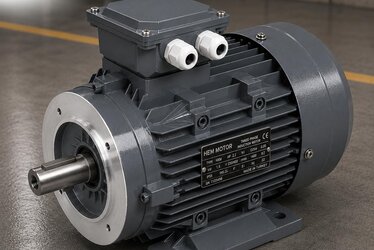
One of the most insidious faults of an asynchronous motor is an earth (frame) leakage. When the winding insulation degrades over time due to moisture, heat, vibration or contamination, a small leakage current begins to flow from the phase conductor toward the motor frame. This leakage is very small at first and the motor appears to be running normally; however, as the insulation breakdown progresses, the leakage grows and eventually leads to a phase-to-earth short circuit and burning of the winding. A properly installed earth leakage protection detects this process while the leakage is still small and disconnects the motor; it both saves the winding and prevents the risk of fire and electric shock.
At the heart of earth leakage protection are two basic components: the zero-sequence CT (core balance current transformer) that measures the leakage current, and the 50N/51N earth fault relay that evaluates this current and issues the trip command. The correct selection of this pair is critical in terms of sensitivity (how small a leakage it sees), selectivity (tripping only the faulty motor) and reliability. As HEM Motor, while supplying asynchronous motors with the correct protection architecture, we recommend an earth leakage protection solution suited to the power and importance of the application. In this article we cover the working principle of the zero-sequence CT, the 50N/51N relay, leakage current limits, the sensitivity-selectivity balance and the correct protection selection.
Why Does Earth Leakage Occur and Why Is It Dangerous?
Earth leakage appears when the resistance of the insulation between the phase conductor and the earthed motor frame drops. The main causes:
- Moisture and condensation: Moisture entering the winding in a stationary motor lowers the insulation resistance.
- Thermal ageing: The insulation of a winding running continuously at high temperature becomes brittle over time.
- Mechanical damage and vibration: The insulation coating of the winding wire can wear away with vibration.
- Contamination: Conductive dust, oil or chemical deposits create a surface leakage path.
Leakage current means that the vector sum of the phase currents is non-zero. In a healthy motor, the sum of the three phase currents (including neutral) is zero; if there is leakage to earth, this sum is not zero, and the difference is exactly the leakage current going to earth. Early detection of insulation breakdown allows the winding to be saved before it burns. We explained how insulation resistance is measured in our article on insulation resistance and the megger test in asynchronous motors.
How Does the Zero-Sequence (Core Balance) CT Work?
The zero-sequence CT is a ring-shaped current transformer that encircles the three phase conductors of the motor (and the neutral, if any) together. Its working principle is simple but powerful: the current of all three phases passes through the transformer together. If there is no leakage, the vector sum of the three phase currents is zero and the transformer produces no current at its output. When there is leakage to earth, the leaking current upsets this balance; a small signal proportional to the leakage current is produced at the transformer output. This signal is sent to the 50N/51N relay.
The biggest advantage of this method is its sensitivity. Even when the phase currents are hundreds of amperes, it can directly measure a leakage of a few hundred milliamps, because the transformer sees only the imbalance (leakage), not the magnitude of the phase currents. There are two basic methods:
- Core balance (summation current) method: A single ring transformer encircles all phase conductors; it measures the leakage current directly. The most sensitive and most common method.
- Residual current method: A separate CT is placed on each phase and the secondaries are summed. Less sensitive, because small differences between the CTs can produce a false signal. Used in high-current systems.
The motor's earthing and EMC connection directly affect the accuracy of the leakage measurement; we detailed this topic in our article on earthing and EMC in motors.
50N/51N Earth Fault Relay: Instantaneous and Time-Delayed Protection
Earth fault protection is referred to by two ANSI function codes. These codes define the behavior of the protection:
- 50N (instantaneous earth fault): The moment the leakage current exceeds the set threshold, it opens the circuit without delay. It provides fast protection for large earth faults.
- 51N (time-delayed earth fault): When the leakage current exceeds the threshold, it waits the set time and then opens. With an inverse-time (IDMT) characteristic, it provides selectivity by opening quickly for a large leakage and slowly for a small leakage.
In practice, good protection uses the 50N and 51N functions together: small leakages are cut with a time delay via 51N, and large faults are cut instantaneously via 50N. This way, unnecessary tripping is prevented during transient conditions (temporary moisture, starting leakage) while a real fault is isolated quickly.
Leakage Current Limit and Sensitivity/Selectivity Table
| Application / Purpose | Typical Leakage Threshold | Function | Delay | Note |
|---|---|---|---|---|
| Life safety (personnel protection) | 30 mA | RCD / 50N | Instantaneous | Where there is risk of human contact |
| Fire protection | 300 mA | 51N | Short delay | Prevents cable/winding leakage fire |
| Small-medium motor insulation monitoring | 0.5-2 A | 50N/51N | Stepped | Early insulation breakdown |
| Large motor / MV | 5-20% of In | 51N (IDMT) | Selective delay | Coordination with upstream stage |
| VFD system | Raised threshold | 50N/51N | Filtered | Beware capacitive leakage current |
If the threshold is set too low, the motor stops unnecessarily (false tripping); if it is set too high, a real fault is detected late. The correct threshold is determined according to the motor power, cable length and the capacitive leakage current of the system.
The Sensitivity and Selectivity Balance
In earth leakage protection, two goals sometimes conflict: being very sensitive (seeing a small leakage) and being selective (tripping only the faulty motor). The ways to strike this balance:
- Graded coordination: The relay at the motor level is set to open faster than the relay at the upstream stage (main busbar); thus only the faulty motor is isolated.
- Accounting for capacitive leakage: Long cables and VFDs produce a small capacitive leakage current even in normal operation. The threshold must be set above this value.
- IDMT (inverse-time) characteristic: Opening quickly for a large leakage and slowly for a small leakage provides both speed and selectivity.
- CT placement: The zero-sequence CT must leave the earthing connection outside; otherwise the measurement is incorrect.
Within the motor's overall protection structure, earth leakage protection complements overcurrent and short-circuit protection. You can find thermal, relay and fuse selection in our article on electric motor protection: thermal, relay and fuse selection, and the motor protection circuit breaker setting in our article on MPCB selection and setting.
Earth Leakage Protection in VFD Systems
In variable frequency drive (VFD) systems, earth leakage protection requires special attention. The high-frequency switching of the drive continuously drives a small capacitive leakage current from earth through the motor cable and winding capacitance. This current is not a real insulation fault; however, a standard earth leakage relay may mistake it for a fault and trip unnecessarily. For this reason:
- On VFD lines the threshold must be set above the capacitive leakage current.
- Where possible, a VFD-compatible (RCM type B or frequency-filtered) earth leakage monitoring device should be used.
- The motor cable should be kept short and the shielded cable correctly earthed.
When correctly installed, earth leakage protection works safely even in a VFD system and catches insulation breakdown early.
The Difference Between Earth Leakage Protection and Insulation Monitoring
Earth leakage protection and continuous insulation monitoring (IMD) are often confused; the two complement each other but work differently. Earth leakage protection measures the leakage from the imbalance of phase currents while the motor is running and opens the circuit when the threshold is exceeded. An insulation monitoring device (IMD), on the other hand, especially in unearthed (IT) systems, continuously monitors the insulation resistance by applying a low-voltage measurement signal between the winding and earth even while the motor is stationary, and gives a warning when it begins to drop.
Using these two approaches together makes the motor's insulation state visible both at standstill and during operation. In critical processes, trending the insulation resistance (planning maintenance if it is gradually dropping) is very valuable for preventing unplanned downtime. Learning how to interpret insulation resistance and its limit values forms the basis for the correct maintenance decision. The following steps guide early intervention:
- Track the insulation resistance trend with periodic megger measurements; a sudden drop heralds a fault.
- Use a space heater to prevent moisture condensation in stationary motors.
- Calibrate the earth leakage protection threshold according to the measured healthy insulation values.
- When the leakage increases, taking the motor out of service and drying the winding or sending it for maintenance prevents the winding from burning.
Earth leakage protection should be considered together with the cable, fuse and contactor protection selected according to the motor's rated current; you can find this calculation in our article on rated current, cable cross-section, fuse and contactor selection.
The Place of Earth Leakage Protection in the Panel
Earth leakage protection is one link in the protection chain of the motor control center (MCC). In a typical motor outgoing feeder, the protection layers are arranged as follows:
- Short-circuit protection: A fuse or motor protection circuit breaker cuts a phase-to-phase short circuit in milliseconds.
- Overload protection: A thermal relay or electronic overload relay protects the motor from continuous overcurrent.
- Earth leakage protection: The zero-sequence CT and 50N/51N relay catch a phase-to-earth leakage early.
- Temperature protection: The winding temperature is monitored directly with a PTC or PT100.
These layers complement each other; none provides full protection on its own. Because earth leakage protection catches insulation breakdown that the other protections cannot see, it is especially critical in humid, dusty and chemical environments. Correct coordination ensures that only the faulty motor stops and the rest of the plant continues to operate.
Correct Earth Leakage Protection Selection: A Checklist
- Is the application life safety, fire protection, or motor insulation monitoring? The purpose sets the threshold.
- Prefer a zero-sequence CT (core balance); it is the most sensitive method.
- Use the 50N (instantaneous) and 51N (time-delayed) functions together.
- Account for capacitive leakage current (long cable, VFD) and choose the threshold appropriately.
- Provide selectivity by coordinating with the upstream stage.
- Only phase (and neutral) conductors should pass through the CT; the earthing should remain outside.
Frequently Asked Questions
What is the difference between a zero-sequence CT and a normal current transformer?
A normal current transformer measures the current of a single phase and gives a signal proportional to the magnitude of the phase current. A zero-sequence CT (core balance), on the other hand, encircles all phase conductors together and measures only the imbalance in the vector sum of the currents, that is, the current leaking to earth. This way it can directly detect a leakage of a few hundred milliamps within a phase current of hundreds of amperes; it is the most sensitive method for earth leakage protection.
What is the difference between the 50N and 51N functions?
50N is instantaneous earth fault protection; it opens without delay the moment the leakage current exceeds the threshold and provides fast protection for large faults. 51N is time-delayed earth fault protection; with an inverse-time (IDMT) characteristic it opens quickly for a large leakage and slowly for a small leakage. Good protection uses both together: small leakages are cut with a time delay, large faults instantaneously.
Why does an earth leakage relay trip unnecessarily on a VFD motor?
The high-frequency switching of the variable frequency drive continuously drives a small capacitive leakage current from earth through the motor cable and winding capacitance. This is not a real insulation fault, but a standard relay may mistake it for one. The solution is to set the threshold above the capacitive leakage, use a VFD-compatible (RCM type B or frequency-filtered) monitoring device, and keep the motor cable short with its shield correctly earthed.
HEM Motor evaluates and supplies asynchronous motors together with an earth leakage protection architecture suited to the power and importance of the application. Share your motor power, cable length and whether your system has a VFD with us; we will provide a quote for the correct zero-sequence CT and 50N/51N protection selection with manufacturer stock advantage and fast delivery.