English
 Türkçe
Taken on its own, grounding an electric motor looks simple: the frame is connected to earth and safety is ensured. But once the motor is driven by a variable frequency drive (VFD), grounding and EMC (electromagnetic compatibility) take on a completely different technical depth. The high-frequency switching (PWM) of the VFD brings up topics such as shielded cable, 360-degree shield termination, common-mode current and the bearing current it causes. In an improperly grounded VFD system, motor bearings can be pitted within months and surrounding devices can suffer interference. In this article we examine motor frame grounding (PE), shielded motor cable in VFD systems, EMC interference management, bearing current and correct connection practices from an engineering perspective.

Motor Frame Grounding (PE) and Basic Safety
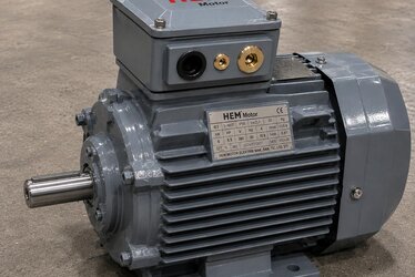
The frame of every electric motor must be grounded with a protective conductor (PE). Its basic purpose is to drain any dangerous voltage that could appear on the frame in case of an insulation fault to earth, ensuring human safety and allowing the protective device (fuse/residual current device) to trip. Motors have a grounding screw inside the terminal box and/or on the frame; the connection must use a suitable cross-section, a clean oxidation-free surface and be firm. For the safety aspect of grounding, our cast-iron motor grounding and electrical safety article explains the basic principles.
In VFD systems, grounding is needed not only for safety but also for EMC and proper operation. Two concepts must be distinguished here: safety grounding (low-frequency, for fault current) and high-frequency grounding/bonding (for EMC, interference). In VFD systems both must be set up correctly.
Why Does a VFD Create an EMC Problem?
The frequency drive produces voltage pulses switched very fast (PWM on the order of kHz) from a fixed DC bus to its output. The rise time of these pulses (dv/dt) is very short, which causes electromagnetic noise (interference) to be emitted over a wide frequency band. This interference spreads in two ways:
- Conducted interference: high-frequency currents carried over cables and earth.
- Radiated interference: electromagnetic fields the cable radiates into the air, acting like an antenna.
This interference can affect sensitive devices such as PLCs, sensors, encoders and communication lines, causing measurement errors and faults. Proper VFD grounding and the use of shielded cable are the basic ways to suppress this interference at its source. For other effects of the VFD on the motor, our VFD and harmonic-related heating and bearing current article is complementary.
Shielded Motor Cable and 360° Termination
Using a shielded (screened) motor cable between the VFD and the motor is the most critical EMC measure. The shield captures the interference the cable radiates and forms a return path so the high-frequency common-mode current returns to the VFD over a controlled route. But for the shield to be effective it must be terminated correctly:
- The shield must be grounded at both ends (at both the VFD and the motor side).
- The connection must be made with a 360-degree circumferential clamp, not just a thin "pigtail" wire. A circumferential termination provides low impedance at high frequency; a pigtail connection raises impedance at high frequency and renders the shield ineffective.
- On the motor side, the shield should be terminated 360 degrees to the terminal box with an EMC gland.
A short, straight cable route reduces interference and voltage reflections. For terminal box and gland selection, our terminal box and cable connection (gland selection) article is useful. To plan the cable entry side relative to the panel, see terminal box orientation and cable entry side.
Common-Mode Current and Bearing Current
The VFD's PWM output produces a voltage component where the instantaneous sum of the three phases is not zero; this is called the common-mode voltage. This voltage creates a common-mode current through the parasitic capacitances inside the motor. Part of this current tries to flow to earth through the bearing because of capacitive coupling between the shaft and the frame. When the oil film in the bearing acts as an insulator, voltage builds on the shaft; once this voltage exceeds a certain threshold it breaks through the oil film and creates a tiny spark (electrical discharge). This is called the EDM (electrical discharge machining) effect.
Repeated discharges form micro-pits and "fluting" marks on the bearing ball and race surfaces; over time the bearing runs noisily, heats up and fails early. If a bearing in a VFD-fed motor fails much earlier than expected, bearing current is a strong suspect. For bearing fault symptoms see electric motor failures: symptoms and causes and for bearing life bearing types and life (insulated bearing).
Methods to Prevent Bearing Current
Several measures are used together against bearing current:
- Insulated bearing: the current path is broken, usually at the non-drive (N) end, using a ceramic-coated or hybrid (ceramic ball) bearing.
- Shaft grounding ring (grounding brush): bypasses the bearing by draining the shaft voltage to earth over a low-impedance path.
- Correct shielding and grounding: returns most of the common-mode current to the VFD over the shield, reducing the current passing through the bearing.
- dv/dt or sine filters: filters at the VFD output soften the sharpness of voltage pulses, reducing the common-mode effect.
In large motors (usually larger frames), insulating both bearings together with a grounding brush should be considered. For details of insulated bearing selection, again our insulated bearing article guides you.
Correct Connection Practices and a Short PE Path
For an EMC-sound VFD motor installation, the following connection practices are important:
- Short, low-impedance PE path: the grounding connections between the motor frame, VFD chassis and panel chassis should be short and wide cross-section (preferably braided copper strap). Long, thin grounding wires show high impedance at high frequency and degrade EMC.
- Star point (single-point bonding): grounding connections should be planned so as not to form a ground loop.
- Separating power and signal cables: the VFD-motor power cable and sensor/communication cables should not run parallel over long distances in the same tray; where they must cross, they should cross at 90 degrees.
- VFD grounding: follow the VFD manufacturer's EMC installation instructions (grounding plate, EMC filter, cable length limits).
These practices should be considered together with the terminal connection and voltage selection. For terminal bridging and voltage selection see terminal connection 230/400V star-delta, and for commissioning steps commissioning checklist.
Efficiency, Cooling and Drive Compatibility With VFD
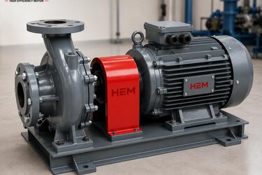
The VFD affects the motor not only in EMC but also in cooling and efficiency. In applications requiring continuous high torque at low speed, the motor's own fan may be insufficient; external forced cooling may be needed. On this topic, our external forced cooling fan (VFD low speed) and general VFD with asynchronous motor articles are useful. For energy savings in pumps and fans with VFD, see VFD savings with the affinity law.
To explore the product family, see our electric motors, for the asynchronous type our asynchronous AC motors and for efficient options our high-efficiency motors categories.
EMC Filter and Cable Length Limits
Most VFDs come with a built-in EMC filter on the input side to suppress conducted interference; in some applications an external filter is added. The EMC filter limits the high-frequency interference currents from coupling into the grid and ensures the device complies with EMC standards (for example a certain emission class). However, the filter alone is not enough; shielded cable, correct grounding and cable length limits must be considered together.
The motor cable length between the VFD and the motor matters for both EMC and voltage reflections. On long cables, PWM voltage pulses can reflect at the cable end and create voltage peaks (overvoltage) at the motor terminals approaching twice the rated voltage; this stresses the motor insulation. Using a dv/dt or sine filter on long cables both protects insulation and reduces the common-mode effect. Each VFD manufacturer specifies maximum length values for shielded/unshielded cable; these limits must be observed. For insulation stress and VFD-related extra loads, our winding and insulation class (F/H) article is useful.
Grounding Systems: TN, TT and IT
The facility's grounding system (TN-S, TN-C-S, TT or IT) affects both how safety protection works and EMC behavior. In a TN-S system the protective conductor (PE) and neutral (N) are separate and provide the cleanest solution for EMC; because no load current flows on PE, only fault and high-frequency currents flow. In a TN-C system, since PE and N are combined (PEN), part of the load current flows over the PE path, which can adversely affect EMC. In sensitive VFD systems, TN-S is preferred where possible. In IT systems, the circuit does not trip on the first fault; while this is an advantage in facilities requiring continuity, it requires special measures for leakage current monitoring and EMC.
Independent of the grounding system, it is a basic rule that the motor's frame grounding be safe and low-resistance. Correct tightening of the grounding screw in the terminal box, a clean non-oxidized contact surface and the use of a suitable lug affect both safety and EMC. For connection details, you can refer again to our terminal box and cable connection article.
Bearing Current Symptoms and Early Diagnosis
Because bearing current damage progresses silently, early diagnosis is important. Typical symptoms are: a high-pitched/whistling sound from the motor bearing that changes with speed; darkening and metal dust in the bearing grease; regularly spaced groove marks (fluting) on the bearing race surface; and the bearing in a VFD-fed motor failing much sooner than expected. Vibration analysis and temperature monitoring help catch this damage early. PT100/PTC sensors and vibration acceptance values are used to monitor winding and bearing temperature; see temperature monitoring with PT100 and PTC and vibration and balance (ISO 10816).
In a motor suspected of bearing current, the solution is to fit an insulated bearing and/or grounding brush, fix the shielding and, if needed, add a filter at the VFD output. During bearing replacement, the correct bearing number and type must be chosen; see bearing replacement and correct bearing number.
Commissioning and Insulation Checks
Before commissioning a VFD system, the motor insulation should be measured with a megger, a grounding continuity test performed and the shield terminations checked visually. Since PWM supply stresses insulation, a sound initial insulation value is important. For insulation measurement see insulation resistance and megger test and for general commissioning steps commissioning checklist. Insulation and grounding checks should also be standard at stock entry and acceptance inspection; see incoming and acceptance inspection. VFD-related harmonics and power quality also cause efficiency loss; see effect of harmonics and power quality on efficiency.
Frequently Asked Questions
Is shielded cable essential on a VFD-driven motor?
In practice it is essential for EMC compliance and interference control. Shielded cable provides a controlled return path for the high-frequency common-mode current; otherwise the interference affects nearby devices and the bearing current risk increases. The shield must be terminated 360 degrees at both ends.
Does bearing current occur in every motor?
No significant bearing current arises in a motor fed directly from the grid; the problem mainly appears with the VFD's common-mode voltage. The risk is higher especially in large-frame, high-dv/dt systems. It is prevented with insulated bearings, a grounding brush and correct shielding.
Is the thickness of the grounding wire enough for EMC?
While cross-section matters for safety, the decisive factor for EMC is the impedance at high frequency. Therefore short, wide and braided (flat) grounding connections are far more effective than a long, thin single wire.
Get a Quote
Contact us for support with correct grounding, shielded cable, insulated bearings and an EMC-compliant selection for your VFD-driven motor. To supply a motor and accessories suited to your application, request a quote on +90 (532) 345 49 86 or via our contact page.
Grounding and EMC Checklist in a VFD System
- Ground the motor frame with PE on a safe, clean surface.
- Use shielded cable between the VFD and the motor.
- Terminate the shield 360 degrees at both ends with a circumferential clamp/EMC gland (do not use a pigtail).
- Make PE and chassis connections short, wide cross-section and braided.
- Separate power and signal cables; cross them at 90 degrees.
- Plan insulated bearings and/or a grounding brush in large/critical motors.
- Use a dv/dt or sine filter at the VFD output if needed.
- Follow the VFD manufacturer's EMC installation instructions.