English
 Türkçe

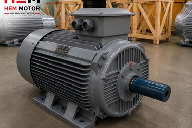
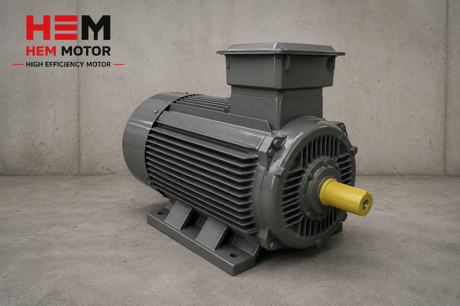
When buying a cast-iron bodied electric motor, most buyers focus on power, speed and efficiency class; the detail of grounding and electrical safety is usually left to commissioning. Yet when the motor body is a conductive material such as cast iron, correct grounding is a matter that must be considered at the moment of purchase, both for personnel safety and for warranty and insurance. As HEM Motor, with our identity as both manufacturer and supplier, we make sure the grounding screw, terminal arrangement and protection class on the cast iron motor bodies we deliver are suited to the application. This article addresses grounding and electrical safety in a cast-iron motor from a purchasing and correct-connection perspective.
Why Is Grounding So Important on a Cast-Iron Body?
A cast-iron body is heavier and mechanically more durable than aluminium; but it is also electrically conductive. When a weakness or leakage occurs in the winding insulation, voltage can pass directly to the motor body. If the body is not properly grounded, a dangerous leakage current can flow through a person touching the motor. Protective grounding, in exactly this case, directs the leakage to earth and lets the protective device (fuse or residual current device) open the circuit. Therefore, on cast-iron motors, body-to-earth continuity is not a luxury but a basic safety requirement. For other advantages and selection of the cast-iron body, see our cast iron vs aluminium body article.
The Role of the Cast-Iron Body in Electrical Safety
Besides its mechanical strength, the cast-iron body shows distinctive behaviour in terms of electrical safety. Because the material is conductive, when properly grounded the entire body becomes a single equipotential surface; that is, no potential difference arises when any point of the body is touched. This is the advantage of the more massive body compared with aluminium: while it carries heat and mechanical impact, when grounded it offers a safe reference surface. However, this advantage only gains meaning with a continuous and low-resistance grounding connection. A painted surface, a poorly contacting screw or a broken conductor disrupts this equipotential structure, and part of the body may remain energised.
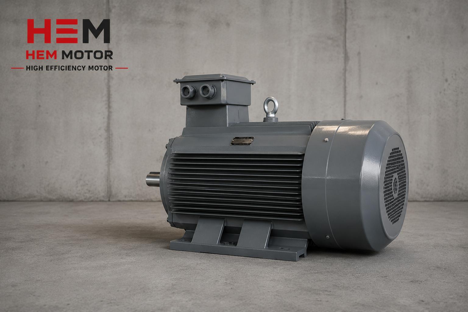
On industrial sites, cast-iron motors are usually in contact with metal chassis, platforms and machine bodies. Although these contact points look like grounding in themselves, they are not reliable; paint, gaskets or connections loosened by vibration do not ensure continuity. Therefore a direct and designed connection from the motor own grounding terminal to the facility protective conductor is always essential. As HEM Motor, we clearly indicate the grounding points on the motor body and provide guidance on this at the ordering stage.
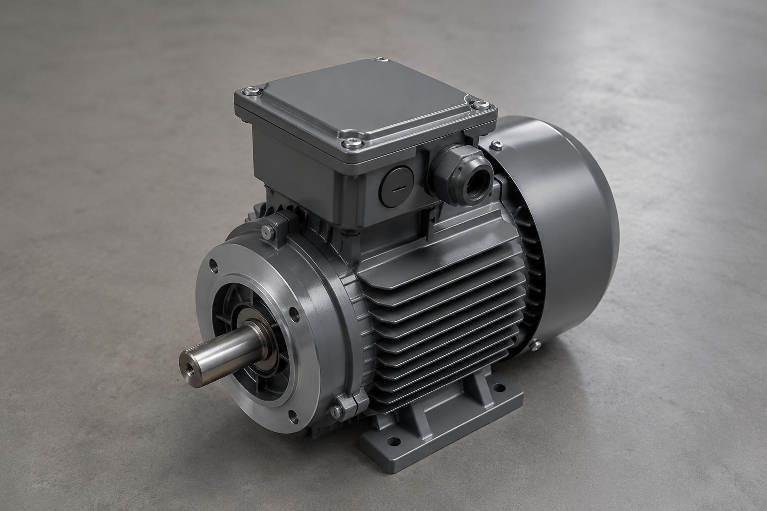
Protective Earth (PE) and the Terminal Grounding Screw
On HEM Motor cast-iron motors, grounding is provided at two points: the grounding screw (PE terminal) inside the terminal box and a second grounding point found on the outside of most bodies. The correct connection is to tighten the green-yellow protective conductor of the supply cable onto the grounding screw in the terminal box so that full contact is achieved. Paint or oxide layer under the screw must be cleaned, and the conductor cross-section must match the phase conductors. Making the terminal box and cable connection correctly also means preserving the IP protection; we detailed this in our terminal box and cable connection article.
At the ordering stage, how many cable entries (glands) the motor requires, the direction of the terminal box and the cross-section of the grounding terminal must be clarified. At high powers a separate external grounding connection may be essential. As HEM Motor, when we quote we ask about these details and recommend a terminal and gland arrangement suited to the project.
Neutral Must Not Be Confused with Grounding
One of the most dangerous misunderstandings in the field is assuming that the neutral conductor and the protective grounding are the same thing. Neutral is a conductor that carries current during normal operation; protective grounding is a separate conductor that is expected to carry current only during a fault and that makes the body safe. Connecting the motor body to the neutral line, even if it appears to work, is a serious safety hole: if the neutral breaks, the body remains energised. For this reason, on a cast-iron motor only the green-yellow protective conductor must be connected to the grounding screw, and it must never be confused with neutral. To grasp the terminals correctly in a three-phase connection, our phase sequence and rotation direction article helps you understand the terminal structure.
The correct connection diagram varies with whether the motor is connected in star or delta and with the supply voltage. This choice affects both performance and safety; our star-delta wiring diagram article explains the terminal connection step by step. The grounding screw, however, must be connected in every case, independently of these power connections.
Body-to-Earth Continuity: The Value to Measure at Commissioning
Tightening the grounding screw alone is not enough; real safety comes from the existence of a low-resistance continuous path between the body and the facility earth. During commissioning, this continuity must be checked with a measuring instrument. Painted surfaces, rusty connections or loose screws raise the continuity resistance and can prevent the protective device from tripping in time. On the first start-up and commissioning checks of the motor, our commissioning checklist article offers a step-by-step check order.
Relationship with Residual Current Protection (RCD)
Protective grounding and the residual current device (RCD/RCCB) work together. When a leakage passes to the body, it flows through the grounding conductor and the RCD detects this imbalance and cuts the circuit. In motors fed by a frequency drive, high-frequency leakage currents can occur, so selecting the appropriate RCD type is important. We recommend requesting motor protection equipment together with the motor; our protection devices purchase article explains this package. For frequency-driven applications, our asynchronous motor with VFD article is also a guide.
Relationship with IP Protection Class
Grounding safety is directly linked to the motor IP protection class. IP55 or higher protection limits moisture and dust ingress into the terminal box, reducing the risk of insulation weakening and leakage. In dusty, humid or open-field environments, choosing the right IP class complements the grounding need. Our IP protection class selection and insulation class in hot and dusty environments articles support this choice.
Grounding Conductor Cross-Section and Connection Quality
The cross-section of the protective conductor (PE) is determined relative to the phase conductor cross-section. As a general rule, at small cross-sections the protective conductor matches the phase conductor; at large cross-sections it is selected at a defined ratio. A grounding conductor of insufficient cross-section heats up during a leakage current and may fail to provide a safe path until the protective device trips. Therefore, when determining the motor power and cable cross-section, the grounding conductor cross-section must be calculated together. Correct cabling is planned according to the rated current on the motor nameplate; for reading the nameplate correctly, our nameplate matching article helps.
Connection quality is at least as important as cross-section. The grounding screw must be tightened to the torque value specified by the manufacturer; a loose connection oxidises over time and raises the continuity resistance. In vibrating applications (crushers, crushing-screening, heavy industry) the risk of screws loosening is higher; therefore periodic checks are recommended. For a periodic maintenance plan, our maintenance and periodic check schedule article offers a framework.
Special Attention to Grounding in Frequency-Driven Systems
In cast-iron motors fed by a frequency drive (VFD), grounding carries a different significance than classic grid supply. The high-frequency switching of the drive can create high-frequency leakage currents in the motor body and cables. In this case, using a shielded motor cable, properly grounding the cable shield at both ends and ensuring grounding continuity between drive and motor are recommended. Otherwise both electromagnetic interference and leakage currents passing through the bearings (bearing currents) can cause problems. This topic must be evaluated together with the drive requirement during motor selection.
What to Ask for Electrical Safety Before Ordering
As HEM Motor, in a cast iron motor quotation we clarify the following points regarding grounding: supply voltage and number of phases, protective conductor cross-section, terminal box direction and number of glands, IP class according to ambient conditions, need for residual current protection, and whether a frequency drive will be used. This information is critical both for a safe installation and for preserving the warranty cover. For the motor frame size and mechanical connection, our frame size and power matching article will be useful. For motor protection on dusty and harsh sites, our stone quarry and mine site motor protection article also complements the topic.
In our range, IE3 electric motor and IE4 electric motor options are offered with a cast-iron body; for mounting type see the electric motor mounting types page, and for geared solutions the worm gear reducers and helical worm gear reducers pages. For more guides see our corrosion protection on cast iron motors article and our homepage.
The Most Common Grounding Mistakes in the Field
During the commissioning of the motors we supply, we see recurring mistakes that weaken electrical safety. The first is not cleaning the paint layer under the grounding screw; in this case, even though the conductor appears connected, no real continuity is achieved. The second is mistakenly confusing the green-yellow protective conductor with neutral, or not connecting it at all. The third is leaving the terminal box cover gasket missing or damaged, allowing moisture and dust to enter and weaken the insulation over time. The fourth is selecting the grounding conductor at an insufficient cross-section.
The common feature of these mistakes is that they give no symptom when the motor first runs; the problem appears only when a leakage occurs or during a periodic measurement. For this reason, measuring and documenting the grounding at the moment of commissioning prevents a possible future accident or warranty dispute. As HEM Motor, when we deliver the motor we provide information about the terminal arrangement and grounding points and guide the correct connection. Our electric motor failures article, where we cover general fault symptoms and causes, also complements these checks.
Documenting the Grounding Measurement and Handover
Especially in heavy industrial facilities such as crushers, crushing-screening, cement and mining, documenting the grounding continuity measurement in writing is increasingly becoming standard. Recording the body-to-earth continuity resistance measured during commissioning and the residual current protection tests protects the business both in occupational safety audits and in a possible fault investigation. These records show that the motor has been safely commissioned from the moment it was received and clarify the chain of responsibility.
As HEM Motor, we clearly share the nameplate data, terminal arrangement and grounding points of the motors we deliver, so the facility electrical team can carry out commissioning correctly and in a documentable way. This approach is also valuable in terms of fleet management, especially in multi-motor facilities; we addressed a similar discipline in our motor fleet management article.
The Relationship Between Grounding, Warranty and Insurance
Electrical safety is not only a technical matter but also a commercial one. A motor damaged because of wrong or missing grounding is most often outside the warranty cover, because the source of the damage is in the installation, not the product. Likewise, in terms of occupational safety, an ungrounded motor can leave the business in a difficult legal and insurance position in the event of an accident. Therefore, planning the grounding arrangement, protection equipment and IP class correctly from the outset when buying the motor protects both safety and the warranty assurance of the investment. As HEM Motor, with our manufacturer and seller identity, we do this planning together at the quotation stage. For details of warranty cover, see our what the electric motor warranty covers article.
Frequently Asked Questions
Is grounding mandatory on a cast-iron motor?
Yes. As with every motor with a conductive body, protective grounding is mandatory for safety on a cast-iron body too. When insulation weakens, the voltage passing to the body becomes safe only thanks to the grounding conductor and protective device. A motor run without grounding poses a risk to life and may also fall outside warranty and insurance cover. At the quotation stage, we plan the correct grounding arrangement together.
Is extra grounding needed besides the terminal box grounding screw?
Many cast-iron motor bodies have a second grounding point on the outside, and connecting this point is recommended especially at high powers. The need is determined by the motor power, the facility grounding system and local practice. When you share the order details, we recommend a suitable terminal and external grounding arrangement.
Does a residual current device protect the motor?
A residual current device (RCD) primarily protects people; by detecting leakage to the body and cutting the circuit, it reduces the risk of electric shock. The motor overload and thermal protection is provided by a motor protection breaker or thermal relay. Therefore, for a safe installation, grounding, RCD and thermal protection should be evaluated together. We can quote the appropriate protection equipment package together with the motor.
Get a Quote
To plan the grounding, terminals and protection class of your cast-iron bodied motor to suit your project, talk to the HEM Motor engineering team. When you share supply data and ambient conditions, we quote the motor with the correct terminals, glands, IP class and protection equipment for a safe installation. Call us now at +90 (532) 345 49 86 or send your request through our contact page.