English
 Türkçe

A significant share of the motor failures encountered in the field originate not from the motor itself but from its connection. Half of a motor is the motor itself; the other half is its correct terminal connection, the right cable gland and the right bridging. A wrongly chosen gland, a loose bridge or an improperly closed terminal box can ruin even a brand-new motor within a few months.
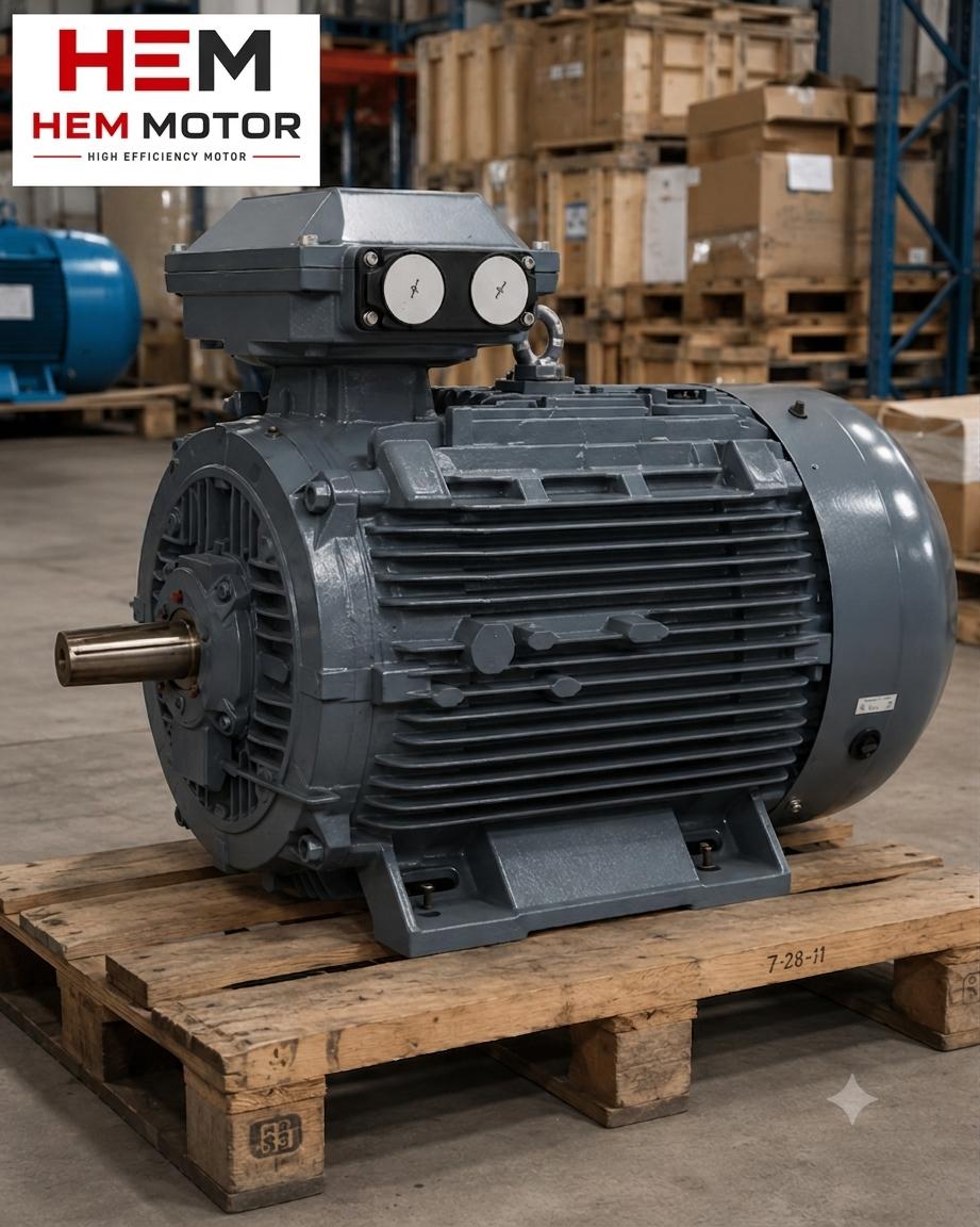
The terminal box is the most critical interface where the motor meets the supply. Three things must be done correctly here at the same time: the cable must enter the box in a way that keeps out water and dust, the terminal bridges must be set for the correct voltage (star or delta), and the box lid must be closed with full sealing. If any of these three steps is skipped, the risk of moisture ingress, short circuit, or running at the wrong voltage and burning the winding arises.
In this guide we cover, in engineering terms, how to correctly perform terminal box and cable connection together with IP protection classes, PG and metric gland selection, star/delta bridging and sealing details. Our goal is to keep the motor running fault-free in the field for years after you buy the right one.
The Purpose and Structure of the Terminal Box
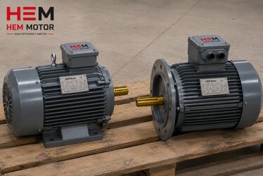
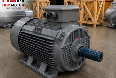
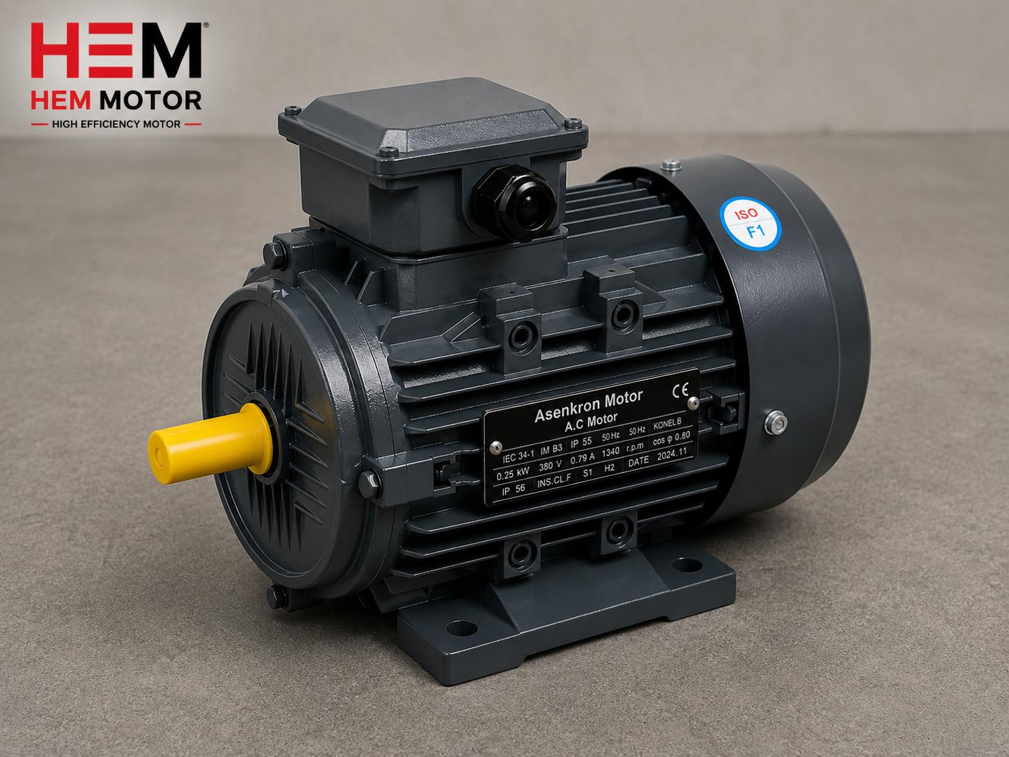
The terminal box is not merely a container where cables are connected; it is also a sealed compartment that protects the motor's internal windings from the outside environment. In cast-iron or aluminium-framed motors the terminal box is usually cast together with the frame and contains a six-terminal terminal block (U1-V1-W1, U2-V2-W2). These six terminals are configured with bridge plates that allow the motor to be connected in star or delta.
The internal volume of the box contains moisture along with air. When the motor runs and heats up and then cools down, this air expands and contracts and draws moist air in from outside; this is called breathing. Over time the water that condenses inside causes corrosion on the terminal block and weakens the insulation. That is why, alongside correct sealing of the box, a breather or anti-condensation measures appropriate to conditions are also important.
- Terminal block: The connection point mounted on an insulator where the winding ends are brought out.
- Bridge plates: The metal bridges that form the star or delta connection.
- Cable entry holes: The threaded (PG/metric) openings where glands are mounted.
- Gasket and lid: The rubber or silicone gasket that provides the IP sealing of the box.
Another important feature of the terminal box is that on most motors it is rotatable. The box can be turned to four different orientations (in 90° steps), so the cable entry can be set to the most suitable direction for the motor's mounting position, preferably facing downward. Correct orientation both eases cable routing and makes it harder for water to enter through the gland outdoors. This simple adjustment is a neglected detail that affects long life in the field.
IP Protection Class: Assurance Against Dust and Water
The IP protection class is expressed with two digits. The first digit indicates protection against solid objects and dust (0-6), and the second indicates protection against water (0-9). The most common value in industrial motors is IP55: strong though not complete protection against dust, and resistance to water jets from any direction. Under harsher conditions, IP65 (complete dust-tight sealing) or higher classes are preferred.
But there is a critical point here: even if the motor frame is IP55, the real protection class of the system drops to the weakest link when the terminal box is closed incorrectly or the wrong gland is used. In other words, an IP55 motor can behave in practice like IP20 because of a loose cable entry. Protection is the quality of the installation in the field, not the number on the label.
- IP55: General industrial environments, enclosed facilities, dusty but non-submerged areas.
- IP65: Outdoor sites, washdown environments, food plants, aggressively dusty areas.
- IP66/IP67: Special applications with intense water jets or temporary immersion risk.
Choosing the Right Cable Gland
Sealing where the cable enters the terminal box is provided by the cable gland. Two standards are common in gland selection: the older PG type (e.g. PG13.5, PG16, PG21) and the modern metric type (e.g. M20, M25, M32). Three parameters are decisive in choosing the right gland: the thread size of the hole in the box, the outer diameter of the cable, and the required IP class.
Common Mistakes in Gland Selection
The most frequent mistake is using a gland that does not match the cable diameter. A gland that is too large cannot clamp the cable and leaves a leakage gap; one that is too small damages the cable insulation. The second common mistake is failing to close unused cable entry holes with a blanking plug; every open hole is a moisture and dust entry that nullifies the IP protection. For broader field practices on correct installation, our content on protecting cast-iron motors against corrosion outdoors is complementary.
- The gland's rubber seal must match the cable diameter.
- All unused holes must be closed with blanking plugs.
- Mounting the gland facing downward outdoors prevents water accumulation.
- The cable must enter the gland without strain (without mechanical load).
Star and Delta Bridging: Correct Voltage Is Vital
The six terminals on a three-phase motor's terminal block can be connected in two ways: star (Y) or delta (Δ). Which one is chosen depends on the supply voltage and the voltage range on the motor nameplate. A common nameplate reads "400/690 V": this means the motor is connected in delta at 400 V and star at 690 V. Wrong bridging is disastrous.
For example, if you mistakenly connect a motor that should be in delta on a 400 V supply in star, the motor runs at low voltage, low power and low torque and cannot lift its load. Conversely, if you connect a motor that should be in star in delta, the windings are over-voltaged and burn out quickly. That is why correct positioning of the bridge plates is the most critical step of installation.
Do Not Confuse with Star-Delta Starting
A point of conceptual confusion deserves attention here: star-delta starting is a starting method in which the motor begins in star at startup and then switches to delta, and it is a different topic. Terminal bridging, on the other hand, determines the motor's continuous running connection. The two concepts are different and must not be confused. When using a soft starter or variable frequency drive in modern facilities, our content on driving an asynchronous motor with a frequency drive is instructive on this topic.
Details That Complete the Sealing
The sealing of the terminal box depends not on a single part but on several complementary details. The lid gasket, the glands and the blanking plugs form a whole; if one of them is missing, the entire system weakens. In motors operating outdoors or in humid environments these details become even more critical, because every drop of water that gets in lowers the insulation resistance and slowly puts the winding at risk.
- Lid gasket: A worn, crushed or missing gasket leaks even when you close the lid. It must be checked regularly.
- Blanking plug: Every unused hole must be closed; otherwise the IP protection loses its meaning.
- Screw torque: Lid screws must be tightened evenly and adequately; over-tightening at one point and under-tightening at another distorts the gasket.
- Cable radius: A cable entering the gland at a sharp angle disturbs the seal pressure; a gentle bend should be left.
Anti-Condensation and Breather
In applications with high humidity, sealing alone may not be enough, because the air inside the box also carries moisture. In this case an anti-condensation heater keeps the inside of the box and frame a few degrees warm and prevents condensation. As an alternative or complement, a controlled breather/drain plug allows accumulated water to be expelled and the pressure to be balanced. Which solution is suitable depends on the motor's running and idle regime.
Grounding: The Neglected Safety Link
A vital part of the terminal connection that is often overlooked is grounding. The grounding screw located in the terminal box or on the frame safely directs leakage current to earth in the event of an insulation fault, protecting both the operator and the equipment. The grounding conductor must be selected in the correct cross-section and its connection kept clean against corrosion. An ungrounded motor can carry dangerous voltage on its frame when the insulation weakens.
- The grounding conductor must be sized to match the phase conductor.
- The connection point must be clean, oxide-free and tight.
- The external grounding point on the frame should also be used.
Post-Installation Checklist
When the connection is complete, the checks that must be carried out before energizing the motor prevent the bulk of future failures. These checks should also be repeated within a periodic maintenance schedule.
- Are the bridge plates set for the correct voltage (Y/Δ)?
- Are the terminal screws tightened to the correct torque value? (A loose connection causes heating and burning.)
- Is there a gland or blanking plug in every cable entry?
- Is the box lid fully seated together with its gasket?
- Is the insulation resistance (megger) measurement at an acceptable value?
At HEM Motor, in addition to supplying the right motor, we provide technical knowledge and support for correct connection in the field. For information about our product range and engineering support, you can visit our homepage.
Frequently Asked Questions
Should I use a PG or a metric gland?
Both provide the same sealing when used correctly. The decisive factor is which standard the hole thread in the motor's terminal box is cut to. Most new motors prefer a metric thread (M20, M25, etc.). What matters is that the gland fits both the hole and the cable diameter exactly.
What happens if I bridge the motor incorrectly?
Incorrect bridging has serious consequences. If you connect delta instead of star, the windings are over-voltaged and can burn out quickly. If you connect star instead of delta, the motor loses power and torque and cannot lift its load. Bridging must therefore always be done according to the supply voltage and the motor nameplate.
Why is water accumulating in the terminal box?
The main cause of water accumulation is the motor breathing as it heats and cools, drawing in moist outside air that then condenses. The solution is correct sealing, closing unused holes with blanking plugs, using a breather or anti-condensation heater if necessary, and mounting glands facing downward.