English
 Türkçe


When a plant invests in an IE3 or IE4 high-efficiency motor, the expectation is clear: less loss, a lower energy bill. But even when the motor is correctly chosen, if the quality of the supplying grid is poor, part of the expected saving disappears invisibly. Harmonics, voltage unbalance, voltage drop and low power factor create extra loss and extra heat in the motor, eroding the field value of the high efficiency on the nameplate. This article looks conceptually at the effect of power quality on the efficiency of a high-efficiency motor: where the hidden losses come from, what eats the IE3/IE4 efficiency gain, and which measures (line filter, reactor, measurement) should be considered to limit these losses. Our aim is to show the conditions that make a correctly bought motor actually run efficiently. We deliberately give no fixed figures or costs here, because every plant's grid, load profile and running hours differ. What is described here is a conceptual framework; the values specific to your plant come only from on-site measurement. Even so, this framework lets you ask the right questions and see which measure is meaningful for you.

What Is Power Quality and Why Does It Concern the Motor?
On an ideal grid the voltage is a perfect sine wave, the three phases are equal and balanced, and the voltage level is constant. In reality the grid deviates from this ideal. Power quality is the measure of how small that deviation is. An asynchronous motor is sensitive to the shape and level of the voltage given to it, because it makes its magnetic field from this voltage. Every defect in the supply turns into an extra loss inside the motor. This is especially important for high-efficiency motors, because the whole design effort of these motors is aimed at reducing losses by a few points; poor power quality can take back those hard-won points. In other words, to use a high-efficiency motor's potential fully, the electricity given to it must also be of good quality. Otherwise a plant can pay for an expensive motor and get the efficiency of a standard one in return.
We covered the motor's behaviour against grid fluctuation and voltage tolerance in our IE3 motor voltage tolerance and grid fluctuation article, and the difference between nameplate and field efficiency in our nameplate vs field efficiency difference content.
Harmonics (THD): A Distorted Waveform
Harmonics are the deviation of the voltage or current wave from an ideal sine. Rectifier loads, frequency drives, LED drivers and other electronic devices in the plant inject harmonics into the grid, distorting the voltage wave. The measure of distortion is expressed by Total Harmonic Distortion (THD). When an asynchronous motor is fed by a harmonic-rich voltage, the harmonic components do not help it rotate; instead they create extra current in the winding and extra iron loss in the laminations. The result is extra heat and falling efficiency. So a high-efficiency motor running on a harmonic-rich grid runs at a real efficiency lower than its nameplate says.
Another insidious effect of harmonics is the extra heat spread through the plant. High-order harmonics create extra loss in the supply transformer and cables too, as they do in the motor; the plant's total efficiency therefore cannot be judged by looking at a single motor. In a plant with high harmonic levels, even the most efficient motors can drown in the losses spread across the whole system. This is why power quality should be treated as a property of the plant's whole electrical infrastructure, not of individual motors.
An important source of harmonics is drives; but when used correctly, a drive also gives large savings on pumps and fans. We covered this balance in our VFD pump-fan energy savings and high-efficiency motor + frequency drive articles. You can find the general selection criteria of a drive-fed asynchronous motor in our frequency drive (VFD) with asynchronous motor content.
Voltage Unbalance: When the Three Phases Are Not Equal
A three-phase motor expects the three phases to be at equal voltage. In practice there can be small voltage differences between phases; this is called voltage unbalance. Though the difference may look small, it produces a disproportionately large effect in the motor: unbalanced voltage creates a reverse-rotating magnetic field component in the motor. This component produces no torque but creates serious extra current and heat in the winding. As a general rule, even a few percent of voltage unbalance can noticeably raise winding heating and lower efficiency. Voltage unbalance often comes from single-phase loads not being shared equally across phases, and usually goes unnoticed. When lighting, socket circuits and small single-phase devices pile onto one phase, that phase is loaded more and a difference appears between phase voltages. This unbalance can grow gradually and, over years, quietly drag down the efficiency and life of motors. The good news is that re-balancing the phase loads is often a low-cost adjustment that gives a direct gain.
We covered the link with the motor's temperature-rise class in our temperature rise class in an asynchronous motor article, and terminal connection and correct voltage selection in our terminal connection and voltage selection content.
Voltage Drop and Low Power Factor
Because of long cables, undersized conductors or overloaded transformers, the voltage reaching the motor can fall below the rated value. At low voltage the motor draws a higher current to deliver the same power; higher current means higher copper loss and more heat. Likewise, when the motor runs at part load the power factor (cos φ) falls; this raises the apparent current drawn from the grid and increases line losses. Low power factor also raises reactive energy draw.
Voltage drop shows up especially on motors at the end of long lines; a motor in the farthest corner from the transformer can be fed at a lower voltage than one close to it. Likewise, when a large motor starts (drawing starting current), the momentary voltage drop on the line can affect other motors on the same line. So voltage drop is a result of the line design, not of a single motor, and must be assessed together with cable cross-section, line length and transformer capacity.
We examined power factor, capacitors and reactive management in our power factor and correction in an asynchronous motor and power factor and reactive penalty in a high-efficiency motor articles. You can find rated current, cable cross-section and protection selection in our rated current, cable cross-section and protection selection content.
Where Do Losses Rise? The Mechanism Inside the Motor
To understand why power-quality defects lower efficiency, it helps to recall the losses inside the motor. A motor's losses are mainly copper loss (in the winding resistance), iron loss (in the laminations), rotor loss, friction and stray losses. Poor power quality affects almost all of these adversely: harmonics raise both copper and iron loss; unbalanced voltage creates extra current in the winding and raises copper loss; voltage drop forces the motor to draw higher current and again raises copper loss. So a single supply defect can swell several loss items at once.
The common result of all these losses is heat. Rising heat not only lowers efficiency but also shortens winding insulation life; every 10 °C of sustained overtemperature roughly halves insulation life. So poor power quality both raises the bill and shortens the motor's life; that is, it does damage both ways, and both forms of damage turn into cost in the long run. We covered where efficiency losses occur as iron, copper and friction in our IE4 motor efficiency losses article.
How Does All This Eat the IE3/IE4 Gain?
The efficiency an IE3 or IE4 motor gives over a standard motor is a difference of a few percentage points. This difference is realised in full if the motor runs in ideal conditions (clean, balanced, rated-voltage supply and a suitable load ratio). But when the defects above combine, the motor runs with extra losses and its real efficiency falls. In the end, even though an expensive high-efficiency motor was bought, the expected saving is not achieved because of poor power quality. This is a loss that shows on the bill but whose cause is often not understood, because the defect is not in the motor but in the supply. Most businesses in this case question the motor or the supplier; yet the place to look is the plant's electrical infrastructure. A power-quality measurement often shows that the motor is actually running correctly but the supply cannot support it well enough.
So switching to a high-efficiency motor means not only changing the motor but also reviewing the supply conditions. We covered the link between correct sizing and efficiency class in our efficiency class and correct sizing article, and the effect of maintenance on motor efficiency in our effect of maintenance on motor efficiency content.
Oversizing: Falling Power Factor at Low Load
Power quality does not come only from the grid; sometimes it arises from the plant's own choices. The most common example is oversizing the motor. A motor chosen far larger than needed carries only a small part of the load and so runs constantly at a low load ratio. In asynchronous motors the power factor falls noticeably as the load ratio drops; at low load the motor draws a disproportionately large reactive current relative to the useful power it produces. This raises line losses and puts the business at a disadvantage in terms of reactive energy. Moreover, because the motor runs below the peak of its efficiency curve, the field efficiency also falls.
So choosing a high-efficiency motor in the correct size is a cheap and effective way to protect power quality. We covered how much load to run a motor at in our motor load ratio, efficiency and correct sizing article, and the effect of part-load efficiency and oversizing in our part and low load efficiency content.
Measures: Filter, Reactor and Measurement
There are concrete measures to limit power-quality losses:
- Line reactor (grid reactor): A reactor connected in series at the drive input or motor smooths current harmonics and voltage spikes, reducing extra heat in the motor.
- Harmonic filter: If the harmonic level across the plant is high, active or passive harmonic filters lower the THD.
- Phase balancing: Sharing single-phase loads equally across the three phases reduces voltage unbalance and the extra heat it causes.
- Compensation (power factor correction): Capacitor banks raise the power factor, lowering line losses and reactive draw.
- Correct cable cross-section: An adequately sized conductor limits voltage drop and the extra copper loss it causes; this matters especially on long lines.
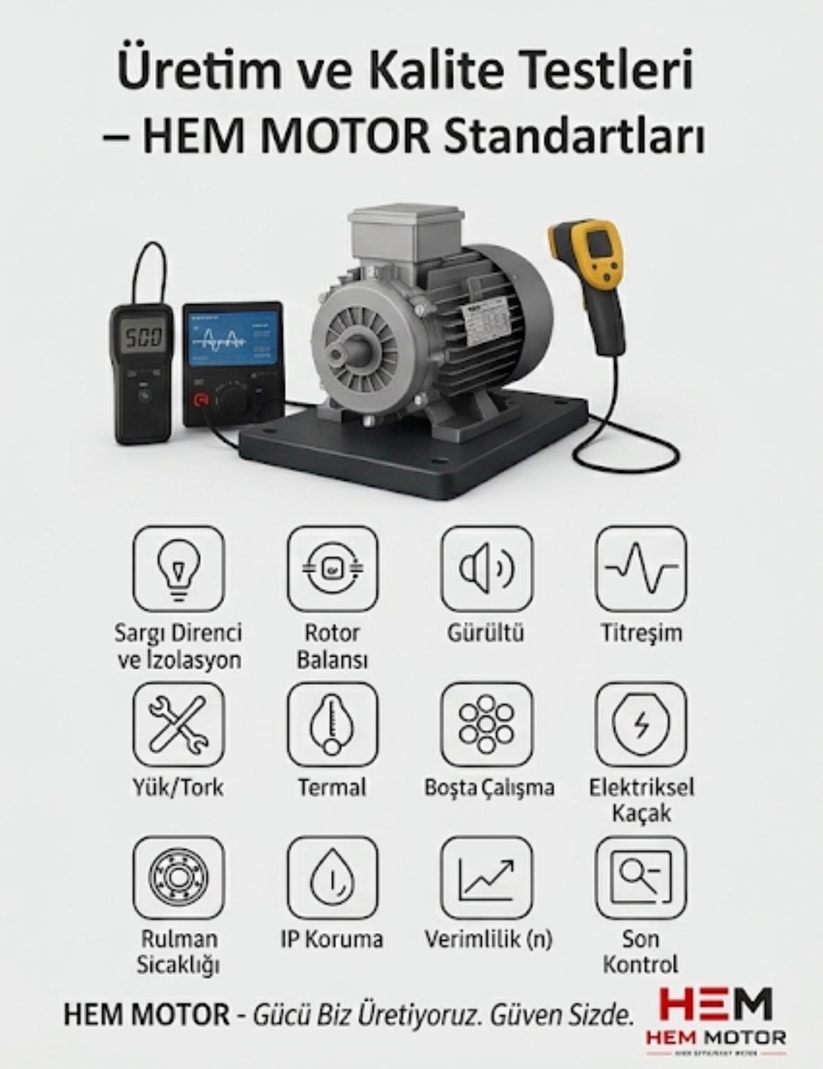
- Measurement: Most important, you cannot improve without measuring. Measuring voltage, current, THD and power factor with a power analyser shows which measure is needed.
We covered measuring and certifying annual energy savings in our measuring and certifying annual energy savings article, and plant motor inventory and efficiency assessment in our energy efficiency audit and motor inventory content. You can reach our range through our electric motors and the HEM Motor home page, and look at the IE3 vs IE4 decision in our IE3 vs IE4 electric motor investment article.
Frequently Asked Questions
I bought a high-efficiency motor but the saving is not what I expected, why?
A common cause is power quality. Harmonics, voltage unbalance, voltage drop or low power factor create losses on top of the nameplate efficiency and lower the real efficiency. Even if the motor is correct, the saving erodes if the supply is poor. Having a measurement made with a power analyser shows the source of the problem and clarifies which measure (reactor, filter, compensation or phase balancing) is needed.
Do harmonics really lower a motor's efficiency?
Yes. Harmonic components produce no torque but create extra current in the winding and extra iron loss in the laminations. This means extra heat and lower efficiency. The higher the THD, the bigger the effect. A line reactor and harmonic filter reduce this effect; these measures matter especially in plants with many drives.
Why is voltage unbalance so harmful?
Even a small voltage difference between the three phases creates a reverse-rotating magnetic field component in the motor. This component produces no torque but creates large extra current and heat in the winding. Even a few percent of unbalance can noticeably raise heating. Sharing single-phase loads equally across phases reduces this problem and is usually a low-cost adjustment; measuring the unbalance makes this easily fixable problem visible.
Get a Quote
Contact us to select a high-efficiency motor and assess your supply conditions; we will define the right efficiency-class motor together according to your plant's real operating conditions. For a fast quote call +90 (532) 345 49 86 or reach us via our contact page.
Checklist: To Protect Efficiency
- Is the voltage level at the motor supply close to the rated value?
- Has the voltage unbalance between the three phases been measured?
- Has the plant harmonic level (THD) been measured with a power analyser?
- Are power factor (cos φ) and reactive draw monitored?
- On drive-fed motors, has a line reactor or harmonic filter been considered?
- Is the cable cross-section adequate to limit voltage drop?
- Are single-phase loads shared evenly across the three phases?