English
 Türkçe
In many applications where the speed of asynchronous motors must be held steady and accurate, the motor's actual speed has to be measured and fed back to the drive. One of the oldest and still widely used solutions for this feedback is the tachogenerator. A tachogenerator is a small DC generator coupled to the shaft; it produces an analog voltage proportional to speed, and that voltage is supplied as speed information to the control system performing speed regulation. Unlike places where an encoder produces digital pulses, the tachogenerator delivers a direct analog voltage; thanks to its simplicity, robustness and compatibility with older systems, it has been used for years especially on DC drives and classic speed-control panels.
This article covers how speed feedback with a tachogenerator works on asynchronous (and industrial motors in general): the analog voltage/speed ratio (V/1000 rpm), its role in speed regulation, its pros and cons compared with an encoder, the mounting (usually rear shaft end / NDE) and coupling details, why it is still preferred in older systems, and how to select the right tachogenerator. The goal is to help you choose the correct feedback component the first time, whether you are upgrading an existing system or building a new speed-controlled drive.
How Does a Tachogenerator Work?
In principle a tachogenerator is a small DC generator. As the motor shaft turns, the tachogenerator's rotor also turns and produces at its output a DC voltage directly proportional to speed. This ratio is constant and is the tachogenerator's most important technical parameter: it is usually expressed in V/1000 rpm (how many volts per 1000 revolutions). For example, a 60 V/1000 rpm tachogenerator produces 60 V at 1000 rpm, 90 V at 1500 rpm and 120 V at 2000 rpm. By reading this voltage, the control system knows the motor's instantaneous speed, compares it with the reference speed and makes the necessary correction.
This linear relationship is the strength of the tachogenerator: there is a simple, predictable link between the output voltage and the speed. The voltage polarity also indicates the direction of rotation; a positive voltage is produced in the forward direction and a negative voltage in reverse. The system thus obtains both speed and direction information from a single analog signal. To keep the signal clean, the ripple at the tachogenerator output is kept low; a quality tachogenerator gives a stable, low-ripple voltage.
- Analog output: A DC voltage proportional to speed, a continuous rather than digital signal.
- V/1000 rpm: The basic parameter that sets the output voltage (e.g. 60 V/1000 rpm).
- Direction information: Voltage polarity shows the direction of rotation.
- Low ripple: A quality tachogenerator produces a stable, clean voltage.
Tachogenerator V/1000 rpm Values and Typical Features
The most important step in tachogenerator selection is choosing the V/1000 rpm value that suits the voltage range the drive expects. The table below shows common values and the approximate voltage they produce at different speeds.
| V/1000 rpm | At 1000 rpm | At 1500 rpm | At 3000 rpm |
|---|---|---|---|
| 10 V/1000 | 10 V | 15 V | 30 V |
| 20 V/1000 | 20 V | 30 V | 60 V |
| 60 V/1000 | 60 V | 90 V | 180 V |
| 100 V/1000 | 100 V | 150 V | 300 V |
As you can see, a high V/1000 rpm value can produce a very high voltage at high speeds. The tachogenerator must therefore be selected according to both the motor's operating speed range and the drive's input voltage limit. A high V/1000 rpm strengthens the signal on a large motor running at low speed, while a lower value is chosen on a high-speed motor to avoid overvoltage. A wrong V/1000 rpm choice leads either to a weak signal or to the drive input being exposed to overvoltage.
| Feature | Tachogenerator (DC Tacho) | Encoder |
|---|---|---|
| Output type | Analog DC voltage | Digital pulse |
| Speed information | Voltage amplitude | Pulse frequency |
| Direction information | Voltage polarity | A/B phase shift |
| Position information | None | Yes (incremental/absolute) |
| At low speed | Signal weakens | Stays stable |
| Typical use | Old/DC drive systems | Modern AC vector drive |
Tachogenerator or Encoder?
The tachogenerator and the encoder work on different philosophies and suit different applications. The tachogenerator produces an analog voltage; it is simple, robust and is the standard especially in DC-driven, older-type speed-control systems. The encoder produces digital pulses; it can also provide position information and is used with modern AC vector drives for high-precision speed and position control. Which is right depends on the system type and the accuracy requirement.
When upgrading an existing DC drive panel or an old speed-control system, if the system already expects a tachogenerator voltage, a tachogenerator of the same V/1000 rpm value is the most practical and compatible solution. If you are building a new AC vector drive and need position control or high precision at very low speeds, an encoder may be more suitable. One limit of the tachogenerator is that at very low speeds the output voltage shrinks and the signal-to-noise ratio weakens; the encoder has an advantage here.
Mounting, Coupling and Mechanical Details
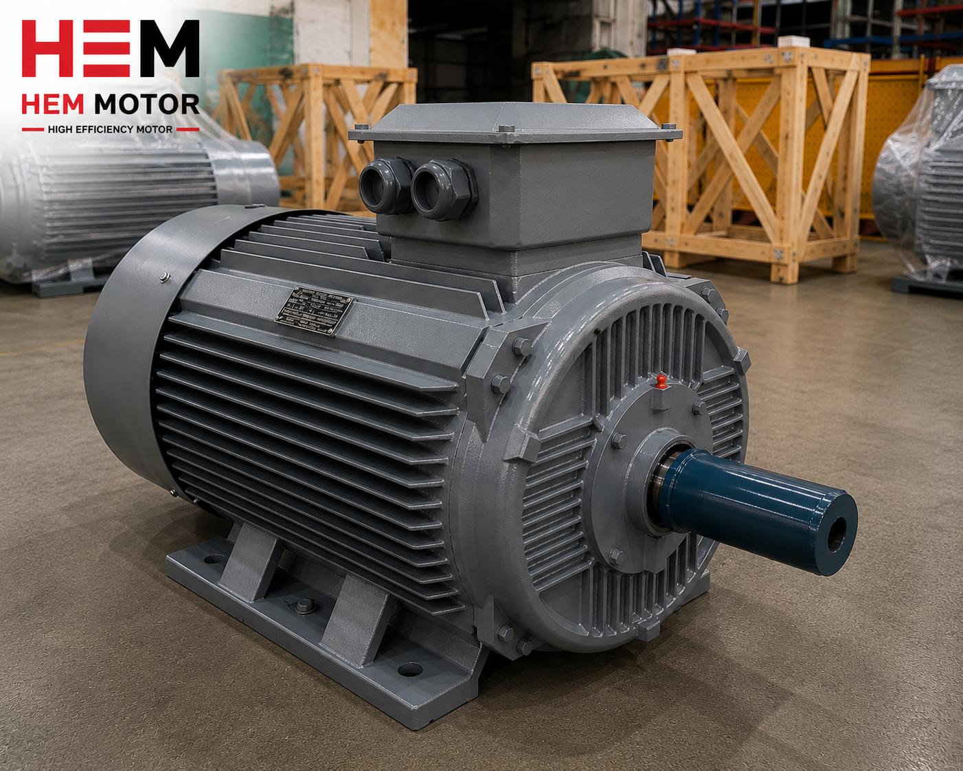
The tachogenerator is usually mounted on the motor's rear shaft end (NDE - non-drive end). Because the drive end (DE) pulls the load, the feedback element is mostly placed on the rear end. For this the motor must have a double-shaft extension (rear shaft end) or a rear cover suitable for tachogenerator mounting. So when ordering a motor with a tachogenerator, the rear shaft end and mounting interface should be specified from the outset.
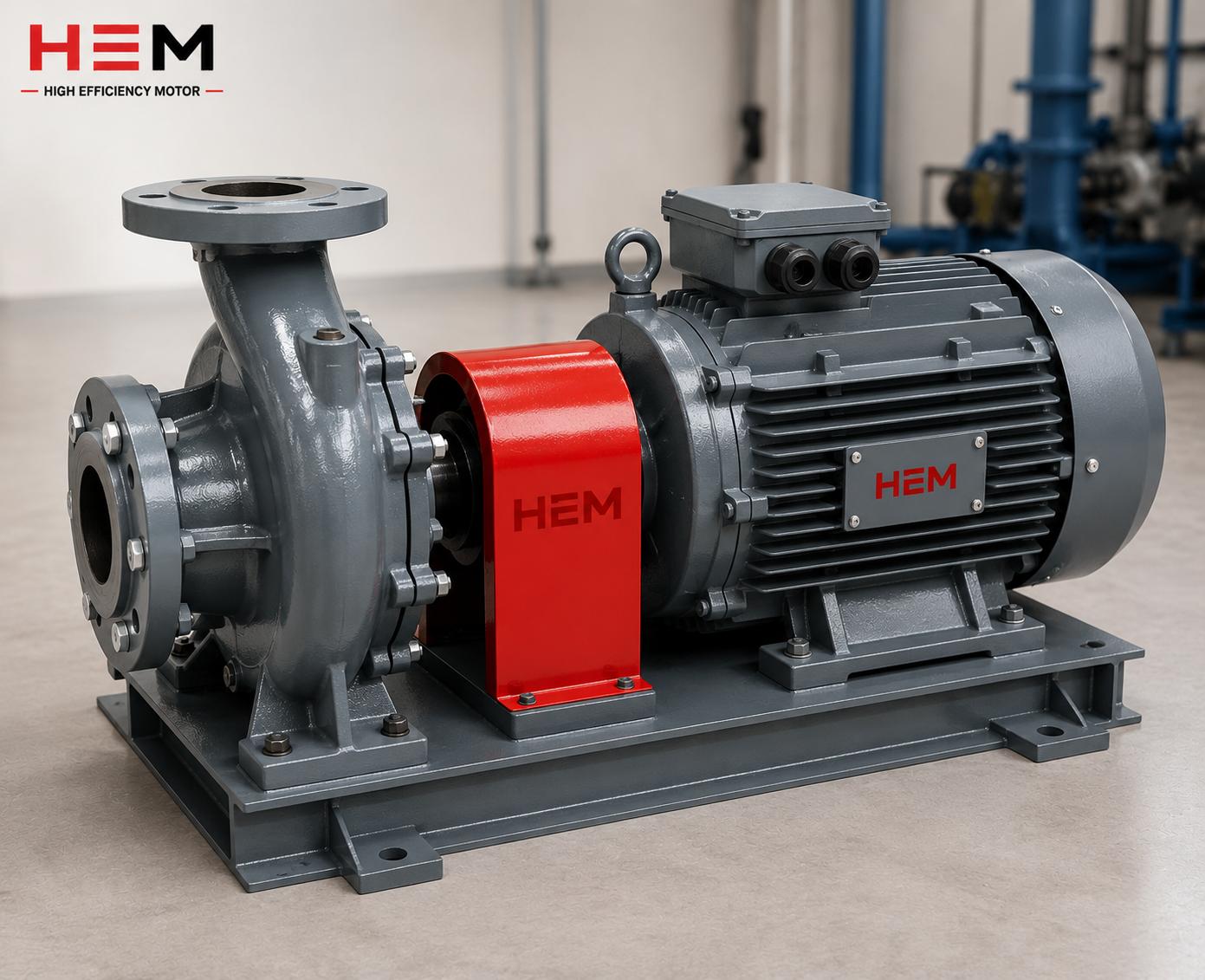
The tachogenerator is connected to the shaft via a coupling. The coupling's job is both to transmit rotation and to tolerate small misalignments. A rigid connection strains the tachogenerator bearing and shaft under misalignment; a flexible coupling is therefore preferred. It is also important that the coupling be backlash-free; otherwise small delays and oscillations can occur in the speed signal. The mounting must be vibration-free, axially aligned and solid, because the tachogenerator produces a very sensitive voltage signal and mechanical defects feed into this signal as noise.
- Rear shaft end (NDE): The tachogenerator is mostly mounted on the non-drive end.
- Flexible coupling: Tolerates misalignment and protects the bearing.
- Backlash-free connection: A backlash-free coupling prevents signal delay.
- Aligned mounting: Vibration and misalignment feed into the signal as noise.
Speed Regulation: Why Is Feedback Needed?
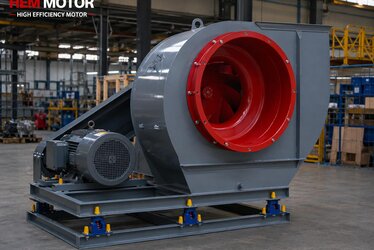
As load increases, an asynchronous motor's slip rises and its speed drops slightly. In an open-loop (feedback-free) system this speed change cannot be controlled; the motor speeds up or slows down a little depending on load. Yet in applications such as extruders, rolling mills, winding lines or paper machines, the speed is required to stay constant even when the load changes. This is where the tachogenerator comes in: it continuously measures the actual speed and reports it to the drive. The drive sees the difference between the measured and reference speeds and instantly corrects its output, so the speed is held constant even as the load varies. This closed-loop structure is the foundation of speed regulation.
The quality of the feedback directly determines the quality of regulation. The cleaner, more stable and delay-free the tachogenerator signal, the more precise and rapid the correction the drive can make. If the signal has noise, ripple or mechanically induced oscillation, the drive mistakes these for real speed changes and makes unnecessary corrections, which causes vibration in the speed. The quality of the tachogenerator, the backlash-free nature of the coupling and the vibration-free mounting are therefore critical details that feed directly into production quality.
- Closed loop: Actual speed is measured, compared with the reference, and the difference corrected.
- Load-independent speed: The speed is held constant even as load changes.
- Signal quality: A clean signal provides precise, stable regulation.
- Precision: A low-ripple tachogenerator gives a smoother speed.
Information to Provide When Ordering a Motor With a Tachogenerator
To correctly supply a motor with a tachogenerator, or a spare tachogenerator, a few pieces of information must be clear. First, the motor's power, speed and mounting type; second, the tachogenerator's V/1000 rpm value and type; third, the mounting interface, that is the motor's rear shaft end and the tachogenerator connection flange; and fourth, the feedback voltage range the drive expects. If you are upgrading an existing system, the old tachogenerator's label data (brand, model, V/1000 rpm, connection type) must be kept exactly the same.
- Motor data: Power, speed, pole count, mounting type.
- Tachogenerator: V/1000 rpm value, ripple class, connection type.
- Mounting interface: Rear shaft end and tachogenerator flange compatibility.
- Drive compatibility: Expected feedback voltage range.
When this information is clear, the motor and feedback component are selected compatibly the first time, and no mounting or calibration problems arise in the field. Especially when upgrading older systems, once the correct V/1000 rpm and mounting interface are matched, the system runs again without requiring any parameter changes.
Why Is the Tachogenerator Still Preferred in Older Systems?
In many plants, DC-driven extruders, rolling mills, winders, cranes and conveyors that have run for years were built with tachogenerator feedback. While these systems run steadily, converting the whole panel logic to digital is both costly and risky. Replacing a failed or worn tachogenerator with a new one of the same V/1000 rpm value is the most practical way to keep the system as is and quickly return to production. The analog nature of the tachogenerator also provides a degree of resistance to electrical noise and simple fault diagnosis; the speed can be checked directly by measuring the voltage.
For the right tachogenerator selection, the motor's speed range, the V/1000 rpm value expected by the drive and the mounting interface must be clear. For more on feedback and speed control, you can review our slip and actual speed in asynchronous motors and scalar and vector control articles. For coupling and mounting, our flexible/rigid coupling selection, for the rear shaft end our double shaft extension and rear shaft end, and for the modern alternative our brake, encoder and forced fan accessories content will be useful.
Frequently Asked Questions
How do I choose the V/1000 rpm value in a tachogenerator?
This value is selected according to the feedback voltage range the drive expects. If you are upgrading an existing system, you must keep the V/1000 rpm value on the old tachogenerator's label exactly the same; otherwise the drive's speed scale is thrown off. In a new system, the voltage produced at the motor's maximum speed must not exceed the drive input limit.
Should I prefer a tachogenerator or an encoder?
It depends on the system type. On DC-driven, older-type speed-control panels a tachogenerator is both compatible and practical. If you need position control, high precision at very low speed or a modern AC vector drive, an encoder is more suitable. If you are keeping an existing tachogenerator system, replacing it with the same type of tachogenerator is the fastest solution.
Where on the motor is the tachogenerator connected?
It is usually connected to the motor's rear (non-drive, NDE) shaft end via a flexible coupling. For this the motor must have a rear shaft end or a tachogenerator mounting interface. Specifying this interface and the speed range when ordering is important for a compatible installation.
At HEM Motor we supply asynchronous motors suited to tachogenerator and encoder speed feedback, with rear shaft end and mounting interface options, including for the upgrade of old DC drive systems, from stock and with fast delivery. Share your motor speed range, the V/1000 rpm value your drive expects and the mounting interface; we will identify the motor and feedback solution compatible with your system and prepare a quotation for the right solution.