English
 Türkçe

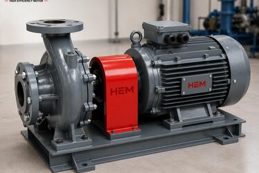
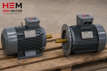
Connecting a motor to a machine may at first glance look like nothing more than bringing two shaft ends together. Yet at the heart of that connection sits the coupling, a critical machine element that directly determines the lifespan, quietness and reliability of the entire system. A wrongly selected or poorly aligned coupling can prematurely wear out the bearings, seals and windings of even the highest-quality, highest-efficiency motor. In this article we examine, from an engineering perspective, the difference between a flexible coupling and a rigid coupling in a motor-machine connection, which one should be preferred in which application, and why correct shaft alignment matters so much.
A coupling does far more than transmit torque. A well-chosen coupling tolerates small shaft misalignments, damps the vibration generated during operation, protects the motor from sudden shocks and overloads, and provides ease of assembly and disassembly when required. For this reason, coupling selection is a decision that deserves as much care as motor selection. While we help you choose the right motor from our stock, we also recommend planning together the right connection solution that will extend that motor's life.
What Is a Coupling and What Does It Do Beyond Transmitting Torque?
A coupling is the mechanical connecting element between the shaft of a motor and the shaft of the driven machine (pump, fan, gearbox, compressor and so on). Its most basic job is to transfer the torque and rotational speed produced by the motor to the driven equipment. In the real world, however, no two shafts are ever perfectly coaxial. Because of manufacturing tolerances, assembly errors, thermal expansion, foundation settling and forces generated during operation, there is always some shaft misalignment between the motor shaft and the machine shaft.
This is exactly where the true value of a coupling emerges. A coupling performs these tasks:
- Torque and motion transmission: It delivers the motor's power to the load with near-zero loss.
- Misalignment tolerance: It absorbs axial, parallel (radial) and angular misalignment within defined limits, reducing stress on the shafts.
- Vibration damping: Especially elastomer-element couplings soften vibration coming from the motor or the load, protecting bearing life.
- Shock protection: It shields the system from shock loads during sudden load changes and start-stop moments.
- Maintenance ease: It allows the connection to be disconnected quickly when the motor or machine must be removed.
Which of these functions stands out depends on the type of application. In a centrifugal pump, vibration damping is paramount; in a crane drive, shock protection may be more critical. Just as much as correct motor selection, how that motor is connected determines system performance.
Flexible Coupling: The Solution That Tolerates Slight Misalignment
A flexible coupling is a coupling type that can tolerate small misalignments between two shafts, containing either an elastic element or a structure that provides mechanical flexibility. It is the most widely used coupling class in industry, because perfect alignment is almost impossible under real assembly conditions and flexible couplings forgive these imperfections to a certain degree.
Types of Flexible Coupling
- Elastomer (rubber-element) couplings: Transmit torque through a rubber or polyurethane element placed between two metal hubs. They excel at vibration damping and run quietly. Frequently preferred in pump and fan applications.
- Pin-bush couplings: Work by pins on one hub entering rubber bushes on the other. Economical and durable.
- Gear couplings: Offer high torque capacity for heavy industry but require lubrication.
- Metal disc (diaphragm) couplings: Maintenance-free, accommodating misalignment with flexible metal discs at high speeds and in precise applications.
- Bellows couplings: Used in servo and positioning systems where torsional stiffness and precision are required.
The greatest advantage of flexible couplings is that they tolerate small alignment errors that can occur during assembly and prevent harmful side forces from passing from shaft to shaft during operation. This directly extends bearing and seal life. In vibration-sensitive applications such as pump electric motors, a flexible coupling is almost a standard choice. The selection criteria on our pump electric motors page will also guide you here.
Rigid Coupling: Precision That Requires Perfect Alignment
A rigid coupling fixes two shafts together almost as if they were a single shaft, offering no flexibility or misalignment tolerance. It does not allow even the slightest misalignment between two shafts; therefore, in systems using a rigid coupling, the shafts must be positioned with near-perfect shaft alignment.
When Is a Rigid Coupling Preferred?
- In applications where the shafts are already supported in a common bearing or single housing and naturally remain aligned.
- In systems requiring very high positioning accuracy and torsional rigidity.
- In situations where axial load must also be transmitted, such as vertical pump columns.
- In precise drives where even the smallest angular deviation introduced by a flexible element is unacceptable.
Rigid couplings are cheap and durable thanks to their simple construction, but they are unforgiving. If an alignment error exists, the full burden of that error rests directly on the bearings, shaft and seals. For this reason, a rigid coupling makes sense only where alignment can be guaranteed. Otherwise, a flexible coupling is always the safer choice.
Why Is Shaft Alignment So Critical?
A significant portion of industrial failures originate from poor shaft alignment. No matter how high-quality or how high-efficiency a motor is, if a constant side force acts on its shaft, its life shortens. Alignment errors fall into three main groups:
- Parallel (radial) misalignment: The two shaft axes are parallel but at different heights.
- Angular misalignment: The two shaft axes intersect at an angle.
- Axial misalignment: The distance between the shaft ends is incorrect.
The consequences of poor alignment include increased vibration, rising bearing temperature, premature bearing failure, seal leakage, rapid wear of the coupling element, energy loss and noise. In practice, most alignment errors are invisible to the naked eye; that is why measurement with dial indicators or laser alignment tools is required. It must also be taken into account that alignment in the cold state can deteriorate at operating temperature due to thermal expansion.
When shaft alignment is done correctly, the load on the bearings is distributed evenly, vibration is minimized, and the motor runs much closer to its rated life. The relationship between asynchronous motor bearing life and alignment is extremely direct; for deeper information you can review our content on asynchronous motor bearing types and life. The effect of alignment errors on seals and sealing is also complemented by our cast iron motor oil seal and sealing protection content.
Practical Tips for Correct Assembly
There are several fundamental rules that prove useful in the field when it comes to couplings and alignment:
- Clean the shaft surfaces, keyways and coupling hubs before assembly; burrs and dirt ruin alignment.
- If heating is required when fitting hubs onto the shaft, heat in a controlled way; forcing with a hammer damages the bearing.
- Use a laser alignment tool where possible; account for shaft sag in dial-indicator measurements.
- Tighten the foundation bolts to the manufacturer's torque and in the correct sequence; add shims under the feet as needed (soft-foot check).
- Anticipating thermal growth at operating temperature, apply the necessary offset during cold alignment.
- Verify that alignment is maintained by measuring vibration and temperature at regular intervals.
These steps may seem minor, but their effect on the motor's total life and operating cost is enormous. After choosing the right motor, commissioning it with the right coupling and the right alignment is the cheapest insurance that protects your investment. To determine together the most suitable motor and connection solution for your application, you can contact us via our homepage.
Coupling Selection Decision Guide
There is no single answer to the flexible-or-rigid question; the decision depends on the application. In summary:
- If you cannot guarantee alignment, if there is vibration, if you drive a rotating load like a pump or fan: flexible coupling.
- If the shafts are naturally aligned, if very high rigidity and positional accuracy are required, if vertical axial load is transmitted: rigid coupling.
- If there is heavy shock load and frequent start-stop: a vibration-damping elastomer flexible coupling.
- If there is high speed and precision: a maintenance-free metal disc coupling.
In every case, the coupling capacity should be selected above the motor's rated torque, and the service factor should be considered. A wrongly sized coupling will fail early even if it is the most correct type.
Coupling Sizing and Service Factor
Selecting the correct coupling type alone is not enough; choosing that type in the correct size is at least as important as the type itself. A coupling should always be sized not by the motor's rated torque alone, but according to the real load profile of the application. For this, coupling manufacturers define a service factor. The service factor determines how much you need to enlarge the nominal capacity of the selected coupling by taking into account factors such as start-stop frequency, shock load, temperature and daily running time. For example, while a low service factor is sufficient for a centrifugal pump running under continuous, smooth load, a markedly higher factor is applied for a crusher that engages frequently or a conveyor carrying heavy shock loads.
The logic of this approach is simple: a coupling must withstand not the average torque it continuously transmits, but the highest peak torque it encounters during operation. At the moment of starting, during a sudden load change or in a jam, the torque reaching the shaft can rise far above the rated value. A coupling enlarged by the service factor safely handles these peaks and prevents premature fatigue of the elastomer element. The key parameters to consider in sizing are:
- Transmitted torque and power: The motor's rated torque is the basis, but the application's peak torque is decisive.
- Duty type and start frequency: In systems that start many times an hour, the elastomer element fatigues more.
- Operating temperature: High ambient temperature reduces the carrying capacity of rubber and polyurethane elements.
- Speed: At high speeds, imbalance and centrifugal forces gain importance; a balanced coupling is required.
- Shaft diameters and keyway: The hub bores must exactly match the motor and machine shaft diameters, and the key connection must carry the torque safely.
A wrongly sized coupling fails early even if the most correct type has been selected. A flexible coupling chosen too small crushes and tears its elastomer element in a short time, while a coupling chosen larger than necessary adds unnecessary weight and inertia to the shaft. The right balance comes from correctly analyzing the application's load profile. For this reason, motor selection and coupling selection should be treated not as two independent decisions but as a single design whole.
Alignment Maintenance and Reading Failure Symptoms
A well-executed shaft alignment is not a task to be set once and forgotten. Foundation settling, thermal cycles, bolt loosening and ground vibration can degrade alignment over time. Therefore alignment should be checked at regular intervals as part of the periodic maintenance program. Especially in high-power, continuously running systems, even a small alignment deviation leads to cumulative damage in the long run. A good maintenance approach requires reading early symptoms before the problem grows.
Typical symptoms that herald a coupling or alignment problem in the field are: increased vibration and noise, abnormal heating in the coupling region, rubber dust shed from the elastomer element, loosening foundation bolts and rising temperature at the motor bearing. None of these symptoms makes a definite diagnosis on its own, but when evaluated together they clearly show that the system needs maintenance. Early intervention prevents a problem that could be solved with a small adjustment from turning into a major bearing or shaft failure.
- Vibration measurement: Regular vibration measurements reveal alignment degradation long before it can be seen by the naked eye.
- Temperature monitoring: A rise in bearing and coupling temperature is an early sign of friction and stress.
- Visual inspection: Cracks, crushing and wear marks on the elastomer element indicate the time for renewal.
- Bolt torque check: It should be periodically verified that the torque of foundation and hub bolts is maintained.
- Spare part readiness: Keeping wearing parts such as the elastomer element in stock minimizes downtime.
In conclusion, choosing the right motor is a beginning; supporting that motor with the right coupling type, the right size and regular alignment maintenance determines the true return on the investment. The answer to the flexible-or-rigid question is not merely a type preference but an engineering decision covering the entire life of the system. Planning together the connection solution best suited to your application's load profile secures both energy efficiency and mechanical durability.
Frequently Asked Questions
If I use a flexible coupling, can I neglect shaft alignment?
No. A flexible coupling is designed only to tolerate small, unavoidable misalignments. It cannot absorb large alignment errors; in that case the flexible element itself wears out quickly and harmful forces still reach the bearings. A flexible coupling is not an excuse for poor alignment but a complement to good alignment. The best result is achieved by combining correct alignment with a flexible coupling.
Is a rigid coupling more durable than a flexible one?
A rigid coupling is structurally simpler and torsionally stiffer, but this does not always make it more durable. If alignment is not perfect, a rigid coupling transfers all the stress directly to the shaft and bearings, leading to rapid failure. So a rigid coupling is durable only under conditions where alignment is guaranteed; otherwise, a flexible coupling provides a longer-lasting system.
How do I decide which motor and coupling I need?
The decision depends on the type of driven machine, speed, torque, duty type, vibration and alignment conditions. If you share your application's load profile with us, we will both recommend the right motor from our stock and determine together the suitable flexible or rigid coupling type and alignment approach for that motor. This way your motor runs trouble-free for as close to its rated life as possible.