English
 Türkçe
When choosing an asynchronous motor to drive a high-inertia load, there is one parameter most purchasing decisions overlook: the load moment of inertia J (kgm²). A large fan impeller, a centrifugal compressor flywheel, a mill drum or a flywheel-equipped crusher all force the motor to draw starting current for a long time as it accelerates from standstill to rated speed. This article takes a commercial look at how to calculate the starting time, compare it against the permissible locked-rotor time, and select the right motor without burning the windings.
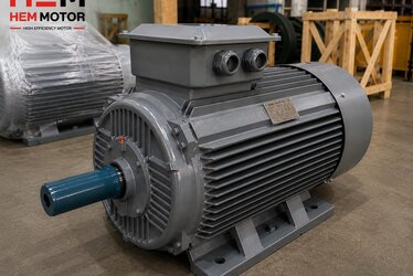
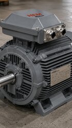
Our goal is not to explain "what inertia is", but to help you select the correct kW, the correct torque class and the correct starting method so that your electric motors investment runs trouble-free in the field. The HEM Motor asynchronous range covers 0.55–355 kW in IE3 and IE4 efficiency classes, with cast iron frames and Class F insulation suited to high-inertia loads.
What Are Moment of Inertia J and GD² (Flywheel Effect), and Why Do They Matter?
The moment of inertia J (kgm²) measures a rotating mass's resistance to acceleration. The same concept appears on older catalogues and nameplates as GD² (flywheel effect, kg·m²). The relationship is simple: GD² = 4 × J. So if the nameplate reads GD² = 8 kg·m², then J = 2 kgm². Missing this small distinction makes your starting-time calculation four times wrong, so clarify the unit before you begin.
The larger the load inertia, the longer the motor takes to "throw" that mass from standstill up to rated speed. A large-diameter centrifugal blower impeller, a heavy mill drum or a flywheel-equipped crusher flywheel are typical high-inertia loads. With these, the motor must draw the starting current (LRA, roughly 6–8 times rated current) for several seconds, and that is exactly where the heating problem arises.
Motor-Side Inertia and Load-Side Inertia Are Calculated Separately
The total inertia that drives the starting time is the sum of the motor's own rotor inertia and the load inertia. However, if a geared motor or belt-pulley is in between, the load inertia is not added directly to the motor shaft; it is reduced by the square of the reduction ratio:
J_load(referred to shaft) = J_load / i²
Here i is the gear or belt ratio (motor speed / load speed). For example, a drum with a load inertia of 50 kgm², driven through a gearbox with i = 5, is reflected to the motor shaft as 50 / 25 = 2 kgm². This reduction is the strongest card for shortening starting time in geared drives. The total inertia referred to the shaft is:
J_total = J_motor + J_load / i²
Starting Time Formula and Calculation Logic
The basis of starting time is Newton's law of rotation: accelerating torque = inertia × angular acceleration. From this the starting time is:
t_start = (J_total × Δω) / M_accel_avg
Δω is the transition from zero to rated angular speed (Δω = 2π × n / 60). The practical engineering formula, in terms of speed (n, rpm), is far more convenient:
t = (J_total × n) / (9.55 × (M_motor_avg − M_load_avg))
The number 9.55 here is the constant 60/(2π). M_motor_avg is the average torque the motor produces during starting; M_load_avg is the average torque the load resists with during starting. The bigger their difference (M_accel), the faster the motor starts. Maximising this difference is the key to saving the motor from overheating, and it is directly related to torque class selection.
Getting the Accelerating Torque Right: The Speed-Torque Curve
An asynchronous motor's torque is not constant across speed; it starts from the locked-rotor torque, rises to the breakdown torque, then drops to the rated point. The load torque also varies with speed: in a fan/pump the torque rises with the square of speed (low at start, high at the end), whereas in a conveyor or mill it is almost constant. To obtain the average accelerating torque correctly, you must overlay the motor and load curves. For curve-reading details see our article on the speed-torque curve and breakdown torque. In practice the average accelerating torque can be taken as roughly 1.3–1.6 times rated torque for Design N motors and 1.8–2.2 times for Design H motors.
Worked Example: 30 kW, 4-Pole Motor, High-Inertia Fan
Let us work through a concrete example. We will select an industrial exhaust-fan drive:
- Motor: 30 kW, 4-pole, 1460 rpm rated speed, IE4.
- Motor rotor inertia: J_motor = 0.25 kgm² (typical 200-frame value).
- Load (fan impeller, directly coupled): J_load = 5.8 kgm².
- No reduction (i = 1), so J_total = 0.25 + 5.8 = 6.05 kgm².
First find the rated torque: M_rated = 9550 × kW / n = 9550 × 30 / 1460 ≈ 196 Nm. (For the detail of this calculation see our rated torque calculation article.)
For a Design N motor, take the average accelerating torque as 1.5 times rated: M_motor_avg ≈ 1.5 × 196 = 294 Nm. The fan load draws on average about one third of rated torque during starting (very low at the start because it rises with the square of speed): M_load_avg ≈ 0.33 × 196 ≈ 65 Nm. Net accelerating torque = 294 − 65 = 229 Nm.
Now the starting time:
t = (6.05 × 1460) / (9.55 × 229) = 8833 / 2187 ≈ 4.0 seconds.
A 4-second start stays within the permissible locked-rotor time (tE) of most standard motors; but if the load inertia were 15 kgm² instead of 5.8, the time would rise to about 10 seconds and that would push the limit. This is exactly the point at which the motor selection must be reconsidered.
Comparison Against the Permissible Locked-Rotor Time (tE)
Your calculated starting time means nothing on its own; you must compare it against the motor's permissible locked-rotor time (tE). tE is the maximum time the motor can withstand, cold or hot, under rated starting current, before reaching the insulation class temperature limit. Motor catalogues give the cold and warm tE values separately.
The basic rule: t_start < tE (hot), and with a safety margin at that. If the starting time approaches the hot tE value, the motor heats cumulatively with every start and winding/rotor life drops quickly. For high-inertia loads this margin is often insufficient, because the starting current (LRA) lasts for seconds. We covered methods for reducing the starting current itself in our article on starting current and LRA reduction; but beware: some methods that reduce the current lengthen the starting time and can worsen the heating.
Consecutive Starts Limit and Cooling
As the starting time lengthens, the number of consecutive starts the motor can perform drops. Each start imposes a heat pulse on the winding; the motor needs to cool between two starts. For high-inertia loads, limits such as "3 starts/hour cold, 2 hot" are common. In applications that need frequent stop-start, this limit becomes critical; we discussed the topic in depth in our starts per hour and thermal and jogging / frequent stop-start articles. The larger the inertia, the lower the permissible starts per hour.
Starting a High-Inertia Load Without Overheating: Solutions
If your calculation shows the starting time approaching tE dangerously, you must change your selection strategy. There are seven approaches that work in the field.
1. A Torque Class With Adequate Starting Torque (Design N / H)
The most direct way to increase the accelerating torque is to select a motor class with higher starting torque. Design H motors produce significantly higher starting and breakdown torque than Design N, which raises the accelerating torque and shortens the starting time. For high-inertia loads, the Design H class often solves the problem on its own. Clarify the class selection from our torque class Design N/H article.
2. Choosing the Right Number of Poles
A lower-speed (higher-pole) motor produces the same power with higher torque and lowers the inertial energy (½ J ω²) because ω is smaller. For high-inertia drives requiring low speed, a 6- or 8-pole motor can create less starting stress than a 2-pole + gearbox solution. Our pole selection 2/4/6 pole article explains this balance.
3. Ramped Start With a VFD (Frequency Drive)
A frequency drive starts the motor from a low frequency and gradually increases it, bringing the starting current down to around rated-current level. Its key advantage: the VFD limits the current without lowering the starting torque by preserving the torque/frequency ratio. This lets a high-inertia load accelerate with low current but adequate torque. In our VFD with asynchronous motor article we covered controlled ramping and heat management. For a high-inertia load, the VFD is often the cleanest solution.
4. Soft Starter — Use With Care
A soft starter reduces the starting current by ramping up the voltage gradually. But as the voltage drops, the starting torque falls with the square of the voltage, which lengthens the starting time. For a high-inertia load, that extra time can increase heating rather than reduce it. A soft starter is suitable for high-inertia loads only if there is sufficient torque margin and the time stays within tE. Star-delta starting similarly cuts the torque to a third; details are in our star-delta and soft starter article.
5. One Size Larger Motor
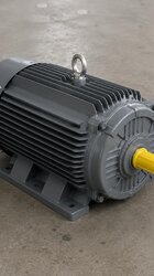
A larger, higher-power motor with a higher rated torque lifts the same load with greater accelerating torque, and because its thermal mass is larger it is more resistant to the heat pulse. For high-inertia and frequent-start applications, sizing the motor up by one or two steps is a practical safety margin. The HEM asynchronous range offers options up to 355 kW; an Ø100 mm shaft is common on the 355 frame.
6. Slip-Ring Motor and Liquid Resistance Starter
For the most demanding high-inertia loads (large mills, heavy crushers), a slip-ring (wound-rotor) asynchronous motor is used. By adding external resistance to the rotor circuit, the starting torque is raised and the starting current is lowered; moreover, a large part of the starting loss is dissipated as heat in the resistance outside the motor, protecting the winding. Our articles on the squirrel-cage vs slip-ring motor and the liquid resistance starter detail this solution.
7. Flywheel and Impact-Load Management
In some applications (hammer mills, crushers) the flywheel is deliberately enlarged; this smooths the impact load during operation but makes starting harder. Here the motor selection, flywheel inertia and starting time must be optimised together. Our hammer mill motor selection article addresses this balance.
Checking Starting Torque in DOL
In direct-on-line (DOL) starting, the starting torque must comfortably exceed the load demand. We covered the relationship between DOL starting torque and rated torque in IE3/IE4 motors in our starting torque / rated torque DOL article. Since the DOL starting current lasts a long time with a high-inertia load, the supply and protection selection must also be made according to this duration.
Relationship With Thermal Class and Braking
A long starting time pushes the insulation's temperature-rise limit (for example 80K); for the right insulation and temperature-rise class selection see our temperature rise class 80K article. Stopping a high-inertia load is as hard as starting it; free deceleration takes a long time. For fast, controlled stopping our braking: DC / dynamic stopping article shows the way.
Frequently Asked Questions
How do I select a motor if I do not know the load inertia?
You cannot calculate the starting time reliably without knowing the load inertia. J can be computed from impeller diameter, mass and geometry; ask the equipment manufacturer for the GD² or J value (remember GD² = 4 × J). If you do not have the value, we start with a safe assumption based on similar applications and then measure the starting time in the field. Share your drive data (kW, speed, load type, impeller diameter/mass, starts per hour) with us and we will determine the inertia match and the correct torque class together.
VFD or soft starter? Which one for a high-inertia load?
For a high-inertia load the VFD is usually the priority, because it preserves the starting torque while reducing the current and keeps the starting time under control. A soft starter is more economical, but because it reduces torque with the square of the voltage it lengthens the starting time and can worsen heating on a high-inertia load. The decision is made according to the inertia value, starts per hour and torque margin.
Does choosing a larger motor of the same power solve the inertia problem?
A one-size-larger motor provides higher accelerating torque and greater thermal mass, so it gives a real safety margin on high-inertia and frequent-start loads. However, it may not be sufficient on its own; it is usually evaluated together with the right torque class (Design H), the correct pole count and, if needed, a VFD. We clarify the best solution with the calculation.
Get a Quote
Are you looking for a HEM Motor asynchronous motor solution for your high-inertia load — one with the inertia matched, the starting time calculated and the heating risk checked? Share your drive data and we will prepare your quote with the right kW, torque class and starting method. Call +90 (532) 345 49 86 or reach us via our contact page. You can review our IE4 motors and sector ranges, and follow asynchronous topics in the asynchronous motor blog category.
Purchasing and Selection Checklist
- Is the load moment of inertia J (kgm²) or the nameplate GD² value known? (GD² = 4 × J)
- Is the motor rotor inertia J_motor taken from the catalogue?
- If a gearbox/belt is in between, was the load inertia referred to the shaft with i²?
- Was the rated torque M = 9550 × kW / n calculated?
- Was the average accelerating torque (M_motor_avg − M_load_avg) taken correctly for the load type?
- Was the starting time t = (J × n) / (9.55 × ΔM) calculated?
- Does the starting time stay within the hot tE (permissible locked-rotor time) with a safety margin?
- Is the required starts/hour below the motor's consecutive-start limit?
- Is the torque class (Design N / H) suitable for the load demand?
- Is the pole count (2/4/6/8) optimised for speed and inertia?
- Is the starting method (DOL / star-delta / soft starter / VFD / slip-ring) selected correctly?
- Does the efficiency class (IE3/IE4) comply with the Ecodesign obligation?
- Do the insulation and temperature-rise class (F, 80K) withstand the long start?
- Are the mounting type (B3/B5/B35) and frame range (56–355L) suitable for the application?
- Is the IP protection class (IP55 standard, IP65/IP66 on request) suitable for the environment?