English
 Türkçe

If you are going to mount a cast iron motor to a gearbox, pump or machine via a flange, a single letter in the order code decides whether the motor will seat on the machine. Is the flange type FF (clearance/through hole) or FT (tapped); is the flange a B5 large flange or a B14 small (face) flange; what are the flange bolt circle (pitch diameter) and outer diameter; all of these must match the connection face of your machine exactly. This guide explains, from a buyer's perspective, the FF and FT flange types on cast iron motors, the B5/B14 mounting difference, the IEC 60072 dimensioning logic, and the correct order code. The goal is to avoid receiving the wrong flange and losing time disassembling and reassembling on site. Giving the correct dimensions once saves both time and shipping cost.
What Are FF and FT Flanges? Clearance or Tapped?
The most critical distinction in a flange connection is whether the mounting holes in the flange are clearance (through) holes or tapped holes. An FF flange (free/through hole) has plain through holes; the bolt passes all the way through the flange and is tightened with a nut on the far side or into a tapped hole in the machine body. An FT flange (tapped hole) has threaded holes in the flange itself, so the bolt threads into the flange. As a general rule the large flange (B5) comes as FF (clearance) and the small face flange (B14) as FT (tapped); however, because this is not always so, the flange type must be stated clearly in the order code.
This distinction matters because the motor is selected according to whether your machine's connection face is designed for a clearance flange or a tapped flange. If the wrong type is chosen the bolt connection cannot be made. We gathered the general logic of flanged motors and mounting codes in our IM mounting code reading (IM B3, IM B5, IM V1) article. We covered the basic selection difference between B5 and B14 in detail in our B5 flange or B14 flange guide.
B5 Large Flange and B14 Face Flange: Which for Which Connection?
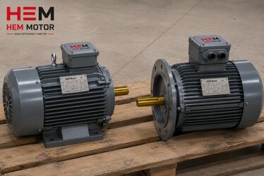
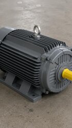
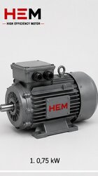
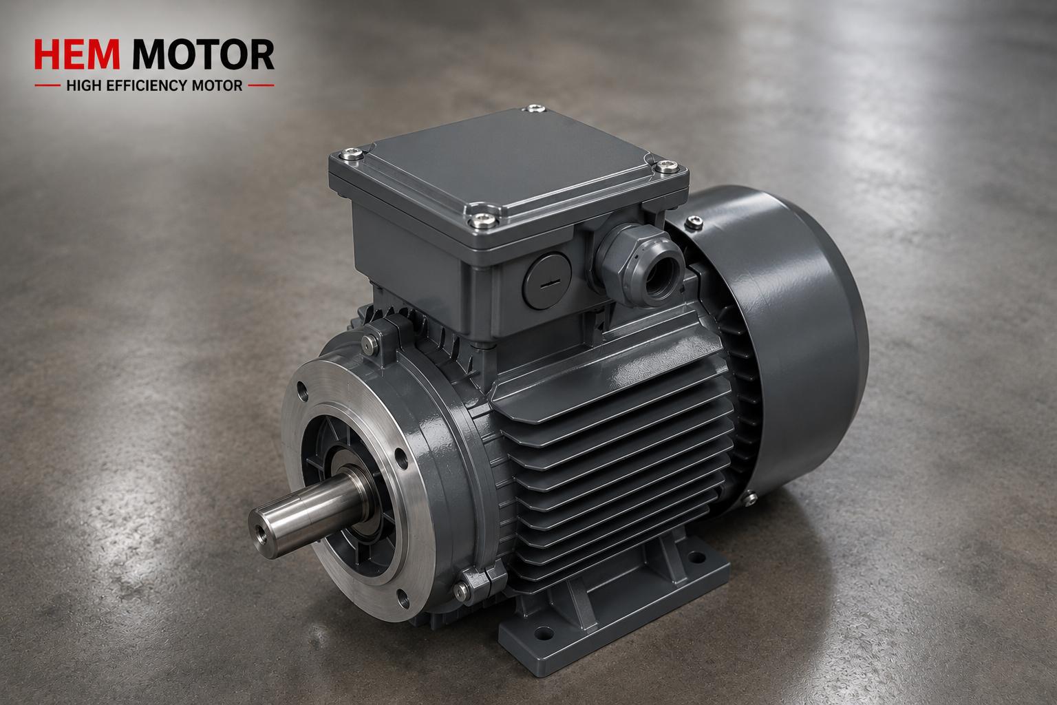
B5 mounting connects the motor via the large-diameter flange on the front cover; the flange is close to the outer diameter of the motor body and is preferred for high torque and heavy machines. A B5 flange is usually FF (clearance) and the bolts pass through the flange into the machine body. B14 mounting (face flange) is a smaller-diameter front flange that does not extend beyond the body; it is usually FT (tapped) and used at low power, on gearbox inputs and in compact machines. In our catalogue B14 flanged motors are offered in the 56–160L frame range and B5 flanged motors in the 63–355L frame range; so B14 is the natural choice at very low power and B5 at high power.
The flange type is especially important for motors that connect to a gearbox, because the gearbox input is made to a specific IEC flange. We explained which motor fits a worm and NMRV gearbox in our worm gear reducer motor matching (IEC) article. We also clarified the question of whether you can fit a B14 in place of a B5 in these articles; flange mismatch is one of the most common ordering errors.
B35 and B34: Foot + Flange Combinations
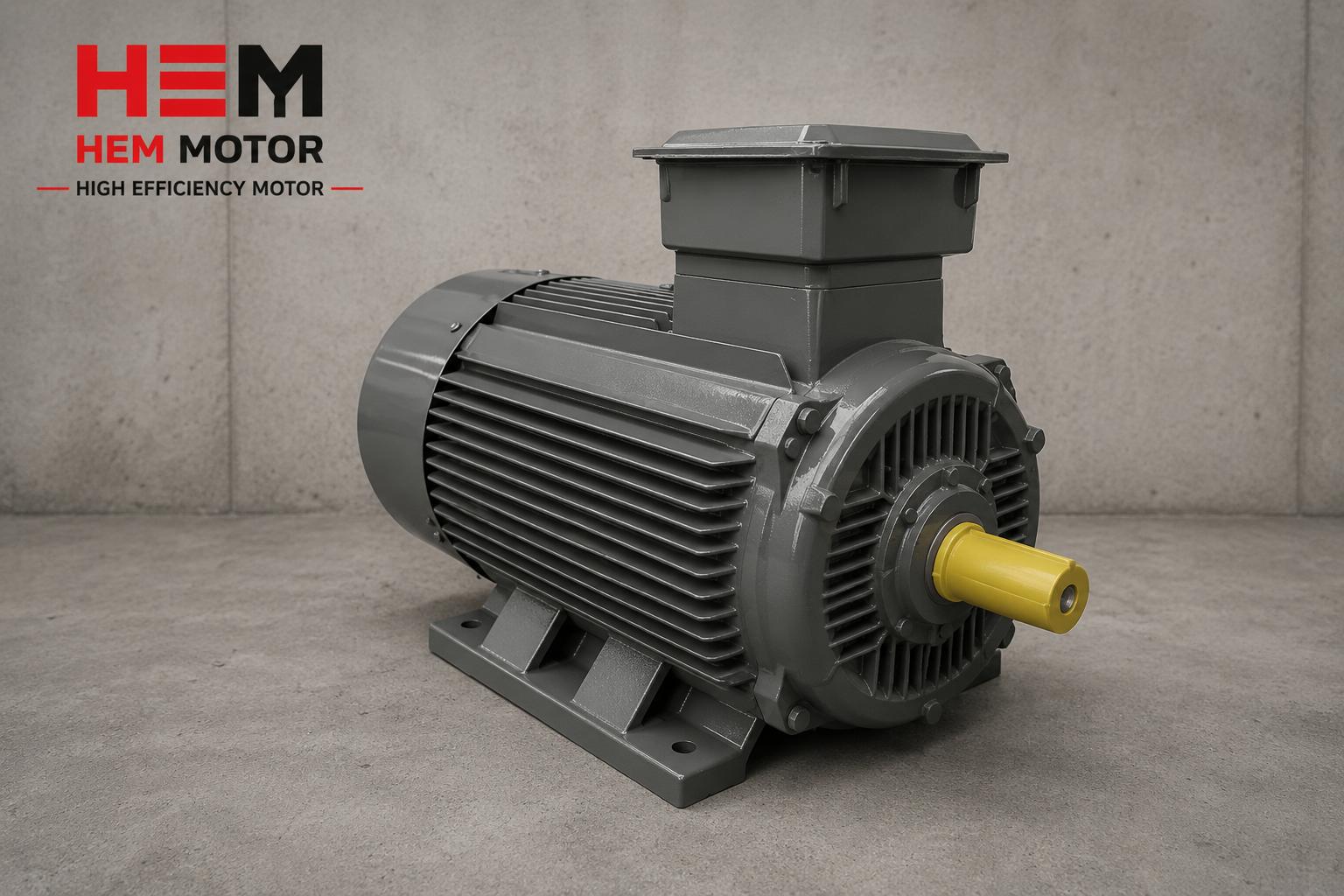
In some applications the motor must connect both by feet to a base and by flange to a machine. B35 mounting is a B3 foot + B5 large flange combination; B34 is a B3 foot + B14 face flange combination. These combinations are preferred when the motor needs extra mechanical support or when both horizontal alignment and a flange connection are required. B34 mounting is offered in our catalogue in the 63–160L frame range. Reading the mounting code correctly is essential when selecting which combination suits your machine.
Flange Hole Dimensions: Pitch (Bolt Circle) and Outer Diameter
For the flange to seat on the machine, two main dimensions must agree: the flange bolt circle diameter (pitch) and the flange outer diameter. The IEC 60072 standard defines these dimensions for each frame size; for a given frame, the flange outer diameter, bolt circle diameter, number of holes and hole diameter are standard values. Thanks to this standard, flange dimensions of different brands in the same frame size are compatible; when replacing an old motor with an equivalent these standard dimensions match exactly. What matters is knowing which frame-size flange your machine's connection face was drilled for.
Besides the flange dimension, the shaft diameter, shaft length and key size must also agree; otherwise the coupling or gearbox input shaft will not seat. We covered shaft and key compatibility in our motor shaft diameter and key dimensions article, and shaft-key-coupling matching on cast iron motors in our cast iron motor shaft, key and coupling article. To see frame size to power matching, our cast iron frame size and power matching guide helps.
Standard Flange Dimensions With IEC 60072 and Equivalent Replacement
Because cast iron motor flange dimensions are made to IEC 60072, it is possible to replace an old brand's motor with a new one exactly; when the same frame size and same mounting code (for example IM B5) are chosen, the flange bolt circle, outer diameter and shaft dimensions all match. This standardization is a great convenience for machine builders and maintenance teams. We described the steps for replacing an old brand motor with an equivalent in our old brand motor direct replacement article, and IE4 equivalent selection with IEC connection dimensions in our IE4 equivalent selection and IEC connection dimensions article.
The machining tolerance and centering quality that a cast iron body provides also affect vibration-free operation of the flange connection. We covered body machining and tolerance in our body machining, tolerance and centering article. You can review the selection difference between cast iron and aluminum bodies in our cast iron or aluminum body guide.
Stating the Flange Correctly in the Order Code
For a correct order, the code must clearly state: mounting type (B5 / B14 / B35 / B34), flange type (FF clearance / FT tapped), frame size (IEC 56–355), power (kW), speed (poles), voltage and, if needed, shaft diameter. To prevent the wrong motor arriving, matching the existing motor's nameplate and flange dimensions is the safest route. We covered this in our avoid wrong motor delivery: nameplate matching article, and the information to provide when requesting a quote in our 8 details to provide when requesting a quote article.
Trouble-Free Mounting With the Right Flange Choice
An order that correctly defines the FF/FT distinction, B5/B14 mounting and IEC 60072 flange dimensions ensures the motor seats on the machine the first time. A wrong flange type means disassembly-reassembly on site, delay and extra shipping cost. You can review all flange and mounting options of our cast iron motors from our cast iron body motors blog category, and technical guides from our electric motor types purchasing map article. For our general products and services, visit the HEM Motor home page.
Centering (Spigot) and Runout Tolerance in Flange Mounting
Another element as important as the bolt circle and outer diameter in a flange connection is the centering spigot (rabbet) in the middle of the flange. This spigot ensures the motor seats exactly centered on the machine or gearbox body; it aligns the shaft axis with the machine axis and prevents vibration. The spigot diameter is also standard per IEC 60072 and is the same value across different brands in the same frame size. Another dimension that determines the quality of the flange connection is the runout tolerance between the shaft end and the flange face; low runout ensures the coupling or gearbox input turns without vibration. The machining quality of a cast iron body is an advantage in holding these tolerances; we covered this in detail in our body machining, tolerance and centering quality article.
If the centering spigot is wrong or worn, the motor runs off-center even when the flange bolts are tight, causing vibration that shortens bearing life. So when selecting an equivalent motor, attention must be paid not only to hole dimensions but also to the spigot diameter. We covered vibration and balance acceptance values in our vibration and balance ISO 10816 acceptance values article, and bearing and journal life on cast iron motors in our bearing and journal life article.
Flange Selection in Vertical Mounting (V1/V5)
Flanged motors are used in vertical mounting as much as horizontal. In shaft-down (V1) or shaft-up (V5) vertical positions the motor is usually connected by its flange; the flange then takes on both the mechanical support role and the connection role. In vertical mounting the oil seal and sealing selection also become important, because the direction of oil and moisture changes. We gathered vertical-mount motor selection and correct ordering in our vertical mounting V1/V5 shaft-down selection article. We explained oil seal and sealing on cast iron motors in our oil seal and sealing article. Stating the mounting code correctly in a vertical application prevents the motor arriving in the wrong configuration.
Verifying the Flange in Gearbox and Machine Connections
The most common use of a flanged cast iron motor is gearbox inputs; so the flange type and dimensions must be verified exactly against the gearbox input flange. The inputs of worm and NMRV gearboxes are made to a specific IEC frame and flange; for example, the HEM frame series in our catalogue match specific motor powers and IEC connection options. If the wrong flange type is chosen the motor cannot be fitted to the gearbox and the order has to be repeated. So for a motor connecting to a gearbox you must check the mounting type (usually B5 or B14), the flange type (FF/FT) and the shaft diameter against the gearbox catalogue. We covered motor matching to a worm gearbox in our worm and NMRV gearbox motor matching article, and the geared-motor vs separate decision in our geared motor or separate article.
Nameplate and Dimension Matching Before Ordering
If you are replacing an existing flanged motor, the safest method is to match the old motor''s nameplate and flange dimensions exactly. The nameplate carries the frame size, mounting code, power, speed and voltage; the flange dimensions (bolt circle, outer diameter, spigot, shaft diameter) must be measured directly. When these come together, the new motor is guaranteed to seat exactly on the machine. We covered preventing the wrong motor with nameplate matching in our preventing the wrong motor with nameplate matching article, and incoming acceptance inspection in our incoming acceptance inspection article. We addressed damage-free handling of a cast iron motor in transport and stacking in our transport, packaging and stacking article.
Frequently Asked Questions
What is the difference between an FF and an FT flange, and which should I choose?
An FF flange has plain through (clearance) holes; the bolt passes all the way through the flange. An FT flange has threaded holes in the flange itself; the bolt threads into the flange. In general the B5 large flange is FF and the B14 face flange is FT. Which you choose depends on your machine's connection face: if the machine body is designed for a clearance flange choose FF, if it expects a tapped connection choose FT. Matching your existing motor's flange type is the safest route.
Can I fit a B14 motor in place of a B5?
Usually no, because the bolt circle diameter, outer diameter and hole type of a B5 large flange differ from a B14 face flange; one does not seat directly in place of the other. If your machine is drilled for a B5 flange you need a B5 motor, and if for B14 you need a B14 motor. Although conversion is sometimes possible with an adapter flange, the most correct solution is to order the motor in the flange type the machine expects. We recommend matching flange dimensions before ordering.
Will the flange match when I replace my old brand motor with a cast iron equivalent?
Yes, because flange dimensions are made to IEC 60072, when the same frame size and same mounting code (for example IM B5) are chosen, the flange bolt circle, outer diameter and shaft dimensions match exactly. This allows motors of different brands in the same frame size to be connected interchangeably. To be safe, send us your existing motor's nameplate and flange dimensions and we will verify the equivalent selection exactly.
Get a Quote
To order your cast iron motor with the correct flange type (FF/FT), correct mounting (B5/B14/B35/B34) and exact flange dimensions, get in touch with us. Tell us your machine's connection face, frame size and power; we will quote the right flanged motor with the correct code the first time. Phone: +90 (532) 345 49 86. For a fast and accurate quote, use our contact page.
Purchasing and Selection Checklist
- Is the mounting type defined (B5 / B14 / B35 / B34)?
- Is the flange type clarified (FF clearance / FT tapped)?
- Which frame-size flange is the machine's connection face drilled for?
- Do the flange bolt circle (pitch) and outer diameter agree with the machine?
- Do the number of holes and hole diameter match?
- Are shaft diameter, shaft length and key size compatible with the machine/gearbox input?
- Is the frame size (IEC 56–355) suited to the chosen power and flange?
- For B14, is the frame in the 56–160L range (per catalogue)?
- If connecting to a gearbox, is matching with the gearbox input flange verified?
- Are the existing motor's nameplate and flange dimensions provided for matching?