English
 Türkçe

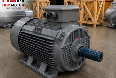
The quality of a cast iron framed electric motor is hidden not only in its winding and efficiency class but in how its frame is machined. Two motors with identical catalogue values behave completely differently in the field when their flange face, bearing seat and shaft machining tolerances differ: one runs quiet and vibration-free while the other produces early bearing failure, coupling wear and noise. Cast iron is not a precise part as it comes from the foundry; the real quality is set by the dimensional and geometric tolerances achieved in the machining (turning, milling, grinding) after casting. This article looks, from a buyer's point of view, at how to judge frame machining quality from dimensions, surfaces and a few simple checks, and at what concentricity, perpendicularity and IEC connection-dimension tolerances actually mean. Our aim is not to give a manufacturing lecture, but to show how a buyer can tell two motors apart on quality with a few simple measurements and observations, without expensive instruments.
Which Surfaces Are Machined on a Cast Iron Frame?
The critical machined surfaces that determine mechanical performance on a motor frame are:
- Bearing seats: The precise bores in the front and rear end shields where the bearings sit. These two seats being on the same axis lets the rotor turn smoothly.
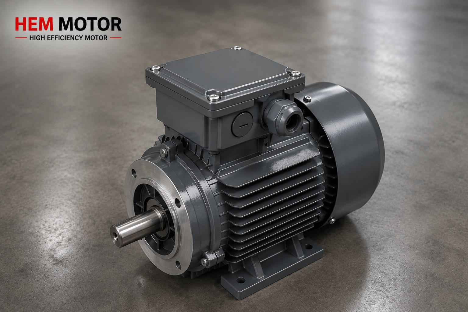
- Flange face and spigot (centring diameter): On B5/B14 flanged motors, the face that bolts to the machine and the spigot that holds the centre. This surface sets the alignment with the driven machine.
- Shaft: The ground cylindrical surface and keyway that enters the coupling, pulley or gearbox input.
- Foot mounting faces: On B3 footed motors, the base faces that sit on the baseplate and must be in the same plane.
Each of these surfaces has a dimensional tolerance (size) and a geometric tolerance (form and position). In quality production these are kept within the limits set by IEC 60072 and related standards. You can find frame-size to power matching of cast iron frames in our cast iron motor frame size and power matching article, and the frame-power relationship in our IEC 56-355 frame sizes content.
Concentricity: Why the Most Critical Dimension?
Concentricity is how well the two bearing seats and the shaft axis lie on the same line. In a motor the rotor turns between front and rear bearings. If the two bearing seats are offset relative to each other, or the shaft deviates from this axis, the rotor produces a magnetic force that varies across the air gap and a mechanical run-out on every turn. The direct result is vibration, noise and a varying load on the bearing. Poor concentricity is the most common manufacturing defect that shortens bearing life.
Think of it with a concrete example: in a 2-pole motor (around 3000 rpm) the rotor turns about 50 times per second. At this speed even a tenth-of-a-millimetre axis offset becomes felt vibration because of the centrifugal force of an unbalanced rotating mass. The higher the speed, the larger the force the same offset produces; this is why concentricity tolerance is even more critical on high-speed motors. On low-speed, high-pole motors the tolerance is a little more forgiving but must still stay within standard limits.
Shaft run-out can be measured even with a simple dial gauge: as the shaft is turned, the deviation at the end is read. On a quality motor this run-out is within the narrow band of a tenth of a millimetre set by standards according to shaft diameter. The same method applies to the flange face: the dial tip is touched to the flange and the shaft turned to read the face's swing (axial deviation). These two measurements give a very strong idea of a motor's mechanical quality without needing expensive instruments. We covered acceptance values for vibration and balance in our vibration and balance ISO 10816 acceptance values article, and the link between vibration and quiet motor selection in our noise and vibration, quiet motor selection content.
Shaft-Flange Perpendicularity and Flange Run-out
On B5/B14 flanged motors the flange face must be exactly perpendicular to the shaft, and the spigot must be concentric with the shaft. If the flange face is not perpendicular to the shaft, when the motor is bolted to a gearbox or pump the shaft is mounted slightly tilted; this creates a constant angular misalignment at the coupling. Angular misalignment, even with a flexible coupling, puts extra radial load on the bearing and shortens the bearing life of both the motor and the driven machine. So the perpendicularity tolerance of the flange face relative to the shaft is at least as important as the spigot on B5/B14 motors. Especially in applications where the motor bolts directly to a gearbox or pump through the flange (no intermediate coupling), a perpendicularity error cannot be compensated; the shaft tilt is transmitted straight to the gearbox input shaft or pump rotor. In these cases flange perpendicularity and spigot concentricity become the two most critical dimensions of the motor. We covered the difference between B5 and B14 connections and which fits where in our B5 vs B14 mounting type selection guide.
We discuss coupling type selection and how shaft alignment compensates these offsets in our flexible vs rigid coupling, shaft alignment article, and shaft diameter, key and coupling compatibility in our cast iron motor shaft diameter, key and coupling content.
IEC 60072 Connection-Dimension Tolerances
IEC 60072 defines the shaft diameter, shaft length, flange diameter, hole pattern and foot dimensions of motors in given frame sizes, and their permitted tolerances. The purpose of this standard is to let motors of the same frame size from different makers be interchangeable. For example, on a 132 frame motor the shaft diameter, foot hole spacings and flange dimensions are fixed by the standard; the tolerance is the narrow band around this nominal value. The real quality of the motor is about where within this tolerance it sits: a frame machined close to nominal and within a narrow band swaps cleanly with its equivalent, while one that exceeds the tolerance produces forcing at assembly, axis misalignment and vibration.
The tolerance has two aspects and both matter. First, how close the dimension is to nominal: if the shaft diameter is 38 mm, the actual diameter must be within a tenth-of-a-millimetre band of this value so the coupling or pulley fits correctly. Second, the fit type: the same nominal dimension behaves completely differently at assembly depending on whether it is a light interference fit or a clearance fit. The standard specifies a fit tolerance field for the shaft (for example k6); if the maker does not comply, the coupling is either forced on or plays with clearance. The practical result for the buyer is this: when ordering an equivalent motor, specify not only kW and speed but also frame size, shaft diameter, shaft length, flange type and mounting code, and confirm that the maker machines these dimensions to IEC 60072.
We covered the importance of these dimensions in direct equivalent replacement in our equivalent selection and IEC connection dimensions and old brand motor direct replacement articles, and the shaft-diameter to frame table in our shaft diameter and frame table (IEC 56-355) content.
Surface Quality: Roughness and Visual Signs
The roughness (surface quality) of a machined surface also reveals quality. If the bearing seat and shaft surface are properly ground, the bearing fit is tight and vibration-free. The bearing seat diameter is also critical: the bearing outer ring must sit in the seat with a defined fit tolerance (usually a light interference or transition fit). If the seat is machined too wide, the bearing outer ring stays loose and turns, wearing the seat; if machined too tight, the bearing is forced in, its internal clearance closes and it overheats. Both lead to early failure. A rough, scored or stepped bearing seat causes the bearing to make micro-movement in the frame (fretting) and wear early. A buyer can tell a lot from a few visual checks on delivery: the flange face must have no burrs, casting sand residue or unmachined areas; the shaft surface must be bright and scratch-free; the spigot must look sharp and truly circular. A poorly machined frame is often visible to the naked eye. Likewise, the terminal box mating face, cover gasket seat and gland holes must be properly machined; roughness here can lower the IP protection class in the field.
The frame's corrosion protection and paint quality are also a sign of manufacturing care; we examined this in our paint and cataphoresis coating article.
Consequences of Poor Machining: Vibration and Bearing Life
The common result of the above defects is clear: vibration rises, bearing life falls. Axis misalignment and flange perpendicularity error put a varying radial load on the bearing; surface roughness creates fretting; shaft run-out produces forcing at the coupling. All of these lead a motor to early failure even if its nameplate says IE3/IE4 and its winding is good. What is more, such failures usually appear not in the first weeks but a few months later; the bearing wears gradually, vibration grows slowly and one day the motor stops unexpectedly. This is why frame machining defects are among the most insidious quality problems: invisible when buying, but they shorten life from the start. So frame machining quality is as concrete a quality criterion as the efficiency class. We collected early failure causes that shorten motor life in our electric motor lifespan and early failure causes article, and the rigidity and impact-resistance advantage of a cast iron frame in our impact resistance and frame rigidity content. Our cast iron vs aluminium frame guide also supports your purchasing decision.
Rotor Balance and the Bearing Seat Together
Frame machining quality alone is not enough; rotor balance also sets vibration. If an unbalanced rotor is fitted in a well-machined bearing seat, the motor still vibrates. Conversely, a perfectly balanced rotor cannot turn smoothly in a misaligned bearing seat. The two work together. In quality production the rotor is dynamically balanced with the key fitted (or half-key), and the balance grade is kept in the class set by standards. So vibration measurement is the most practical acceptance test that gives an idea of both frame machining and rotor balance at once. Running the motor off-load and measuring vibration on delivery reveals many manufacturing defects that are invisible to the eye. We covered the split of magnetic, mechanical and aerodynamic noise sources in our asynchronous motor noise sources article, and the symptoms of rotor-related defects such as broken rotor bars in our broken rotor bar and quality content.
Foot Flatness and the Mounting Surface (B3 Motors)
On B3 footed motors the four foot mounting faces must be in the same plane. If one foot is at a different height from the others (soft foot), the frame twists slightly when the motor is bolted to the baseplate. This twist distorts the axis of the bearing seats and again leads to vibration and bearing stress. On a well-machined frame the four feet are machined in the same plane in a single setup; this lets the motor sit cleanly even on a slightly imperfect baseplate in the field. At assembly, flatness can be corrected by placing thin shims under the foot, but this hides the manufacturing error rather than solving it. We covered the importance of this in continuously loaded applications such as heavy-duty conveyor drives in our cast iron heavy-duty conveyor drive motor article. For grounding and electrical safety the connection surfaces on the frame must also be properly machined; we explained this in our cast iron motor grounding and electrical safety content.
You can reach our range through our electric motors and the HEM Motor home page, and look at cast iron frame options in our cast iron vs fabricated steel frame article.
Frequently Asked Questions
How can I tell frame machining quality before buying?
A few simple checks say a lot: measure shaft run-out with a dial gauge, check the flange face for burrs and casting sand residue, confirm the spigot is sharp and circular and the shaft surface bright and scratch-free. If possible, ask the maker for dimensional and vibration measurement values.
Why is concentricity so important?
If the two bearing seats and the shaft are not on the same axis, the rotor produces vibration and a varying load on the bearing on every turn. This is the most common manufacturing defect that shortens bearing life. Quiet, long-lived operation depends directly on good concentricity.
What does IEC 60072 tolerance guarantee in equivalent replacement?
IEC 60072 standardises the shaft, flange and foot dimensions of motors of the same frame size. A motor machined to tolerance can swap mechanically one-to-one with another brand's same-frame motor; there is no forcing or axis misalignment at assembly.
Get a Quote
Share the frame size, mounting type (B3/B5/B14/B35) and power-speed you need; we will quote your precisely machined cast iron framed motor with the correct connection dimensions. For a fast quote call +90 (532) 345 49 86 or reach us via our contact page.
Purchasing Checklist
- Are the frame size and mounting type (B3/B5/B14/B35) clear?
- Are shaft diameter, shaft length and key dimensions compatible with the driven equipment?
- Are flange diameter, spigot and hole pattern to IEC 60072?
- On delivery, were shaft run-out, flange face and spigot checked visually/dimensionally?
- Are the bearing seat and shaft surface quality (smoothness) adequate?
- Were dimensional and vibration measurement values requested from the maker?
- Is the corrosion protection/paint suitable for the operating environment?