English
 Türkçe
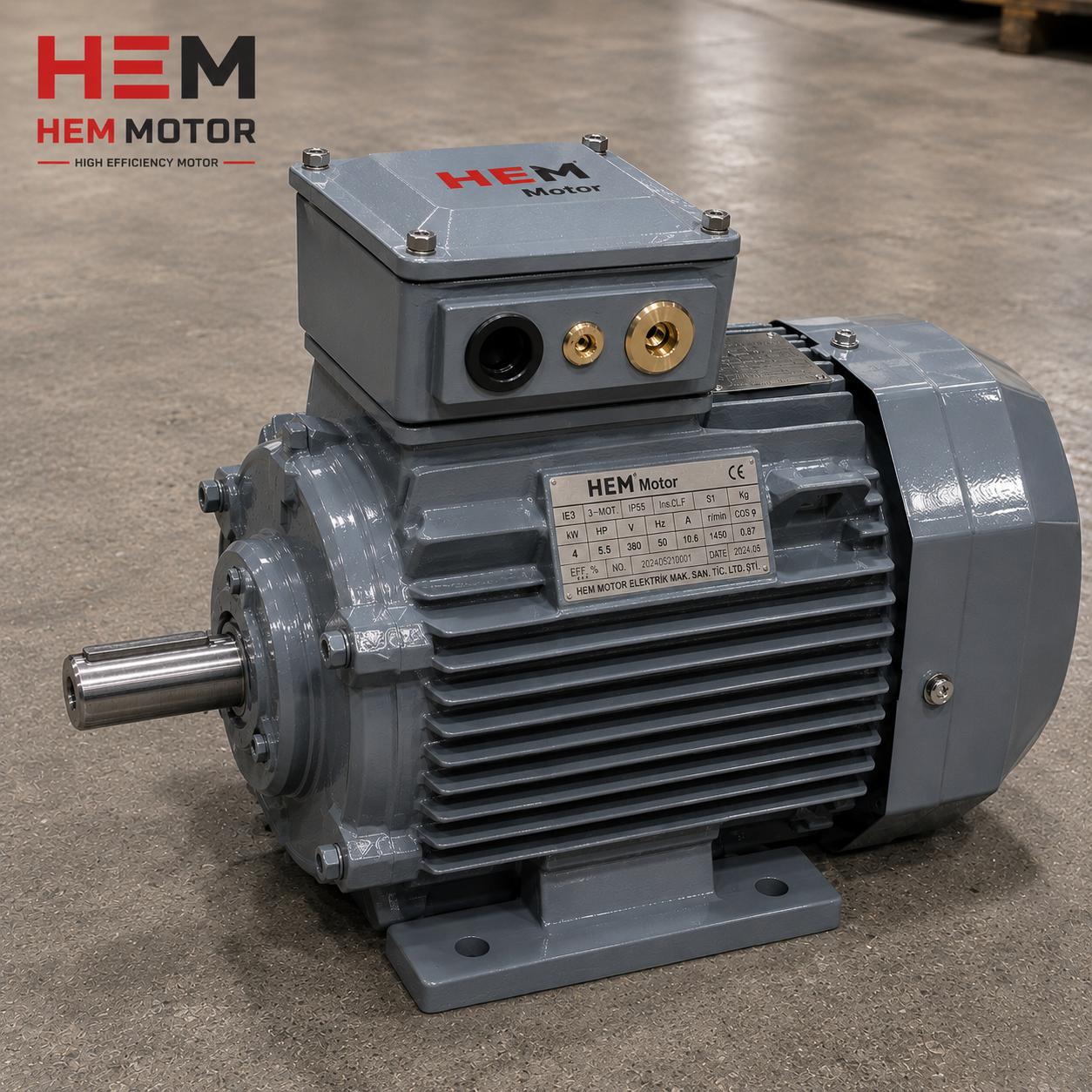
When you open the terminal box on an IE5 synchronous reluctance motor, you often see another separate and usually smaller box next to the main power terminals: the second or auxiliary terminal box. This box does not carry power to the rotating part of the motor; inside it are the terminals of auxiliary signals such as temperature sensors (PTC, PT100), an anti-condensation heater (space heater), a brake, an encoder and similar items. There is a very concrete engineering reason for keeping it separate from the main power terminals: IE5 synchronous reluctance motors always run with a drive (VFD), and the high-frequency noise generated at the drive output can corrupt sensitive sensor signals. In this article we cover what the second/auxiliary terminal box on an IE5 synchronous reluctance motor does, which signals are gathered here and why, the importance of EMC and signal separation, the mounting position and the correct option selection.
At HEM Motor, while delivering IE5 synchronous reluctance motors together with drive packages from stock, ordering the auxiliary terminal box correctly and wiring it correctly in the field is critically important for the life and reliability of the motor. Wrongly grouped signals cause a system failure, not just a motor failure.
Why Is the Second/Auxiliary Terminal Box Kept Separate?
The main power terminal carries the phases (U, V, W) and the ground; here hundreds of volts and tens of amperes of power flow. In an IE5 motor fed from a drive, these power lines carry high-frequency voltage changes (du/dt) and electromagnetic noise due to switching. Sensor signals, on the other hand, are very sensitive analog or low-level signals on the millivolt scale. When power and signal come together in the same box and the same cable bundle, the noise on the power line couples onto the sensor signal; the PT100 temperature reading goes haywire, encoder pulses are corrupted and the protection relay trips falsely. For this reason manufacturers gather sensitive signals in a physically separate auxiliary box.
This separation is directly related to du/dt and terminal voltage spikes; we examined output filtering and voltage spike management on IE5 motors in our article on output sine filter and du/dt. Correct grounding and EMC connection is also critical for this box; our article on grounding and EMC is complementary.
Which Signals Are Gathered in the Auxiliary Box?
The signals gathered in the auxiliary terminal box vary with the motor options. Typical content is as follows:
| Signal/Element | Function | Typical Connection |
|---|---|---|
| PTC thermistor | Instant protection at winding overtemperature | 2-wire, threshold resistance |
| PT100 (RTD) | Winding/bearing temperature measurement | 3-wire, analog |
| Anti-condensation heater | Prevents condensation on a stopped motor | Separate supply (e.g. 230 V) |
| Encoder/resolver | Speed and position feedback | Shielded multi-core cable |
| Brake coil | Brake supply on a brake motor | DC/AC supply |
| Forced-cooling fan | Cooling fan supply at low speed | Separate power supply |
Some of these signals are analog and very sensitive (PT100, encoder), while some are low-level but can still be affected by noise (PTC). Elements such as the anti-condensation heater and forced-cooling fan are actually small power consumers; on some motors these may also be gathered in a separate, third box. We compared the differences between temperature protection elements in our article on bimetal, PTC and PT100 thermal protection.
Why Is the Anti-Condensation Heater (Space Heater) Important?
IE5 synchronous reluctance motors often run in variable-speed applications that stop intermittently. When the motor stops, the body cools and, in a humid environment, condensation forms on the winding surface. This moisture gradually weakens the winding insulation and leads to an insulation fault. The anti-condensation heater comes on when the motor stops and keeps the body a few degrees above the ambient temperature, preventing condensation. The heater supply is independent of the main power and is usually commanded from the panel to energise automatically when the motor stops. We explained this in detail in our article on anti-condensation heater and moisture protection.
EMC and Signal Separation: Critical in Drive Operation
An IE5 synchronous reluctance motor cannot run without a drive; this is why the auxiliary box design takes EMC into account from the start. In correct practice:
- Power cables and signal/sensor cables are routed along separate paths; they must not run side by side in the same cable tray.
- Encoder and PT100 cables must be shielded, with the shield grounded at a single point (usually on the drive side).
- The anti-condensation heater supply must be cut while the motor runs; otherwise there is a risk of overheating.
- The cable gland entries of the auxiliary box must be EMC-compatible and the shield continuity must not be broken.
During drive parameterisation and commissioning it must be checked that the sensor signals are read correctly. We described the drive parameterisation steps on IE5 motors in our article on drive parameterisation and commissioning. Shaft grounding and bearing current protection must also be planned together with the auxiliary box wiring; our article on shaft grounding and bearing current provides guidance on this.
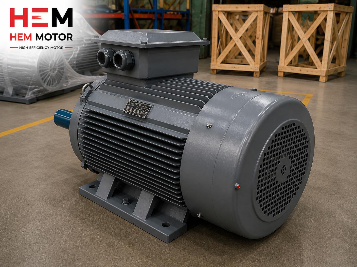
Mounting Position and Access
The auxiliary terminal box is usually located next to the main terminal box or on a different face of the body. At the ordering stage the box orientation must be determined according to the panel side and cable route; an auxiliary box facing the wrong way leads to the shielded cable being run longer than necessary and to noise coupling. For PT100/RTD 3-wire connection details our article on PT100 3-wire connection and for multi-channel sensor selection our article on PT100/PT1000 and RTD scanner are helpful.
Correct Option Selection
Which elements the auxiliary box contains is decided at the ordering stage. Unnecessary options increase cost, while missing options cannot be installed later in the field (especially PT100 embedded in the winding is fitted at the factory). For this reason:
- Choose the temperature protection level according to the application: continuous monitoring with PT100 in critical processes, or PTC may be enough for simple protection.
- Always request the anti-condensation heater in humid or intermittently stopping applications.
- If closed-loop speed control is required, specify the encoder/resolver option from the start.
- Consider a forced-cooling fan in applications that need continuous torque at low speed.
The Auxiliary Box and the Thermal Behaviour of the Motor
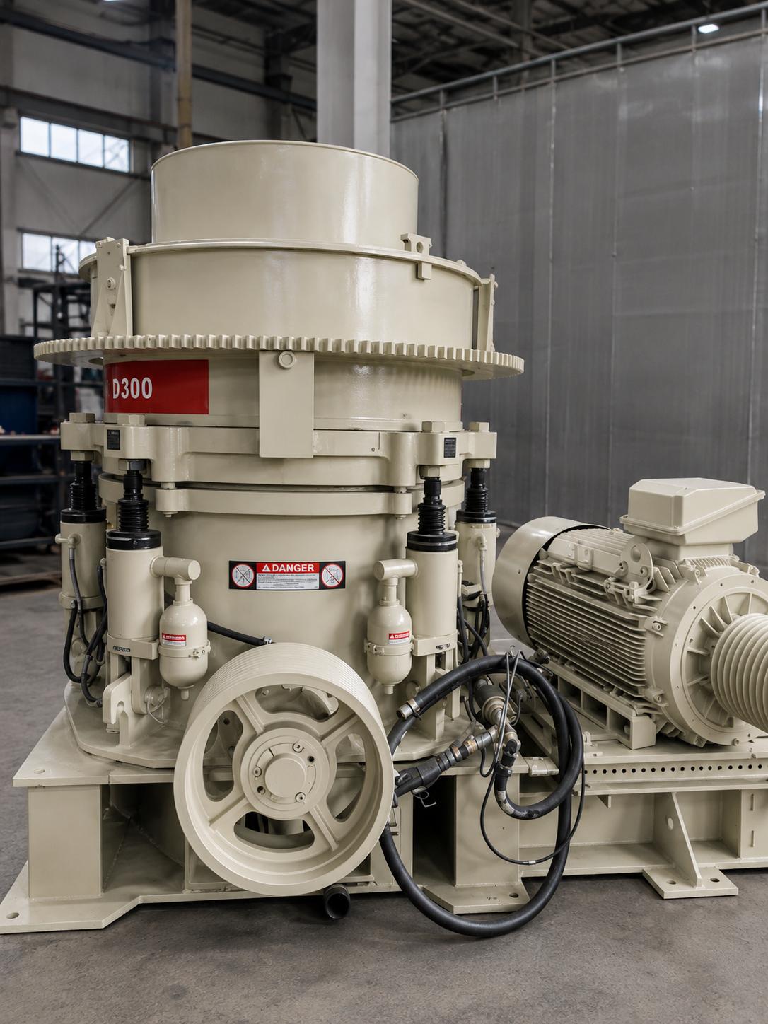
IE5 synchronous reluctance motors are highly efficient, meaning they produce fewer losses at the same power; however, since they are fed from a drive, the flow of the cooling fan also drops at low speed. In this case, continuous monitoring of the winding and bearing temperature reveals the real value of the PT100 sensors in the auxiliary box. By carrying the temperature data to the drive or the panel protection relay, the speed can be reduced or an alarm raised when the motor approaches its thermal limit. We examined thermal behaviour and the correct sizing of cooling on IE5 motors in our article on thermal behaviour and cooling. Grease and torque behaviour at a cold start is also related to the auxiliary options; we addressed this in our article on cold first start.
The encoder or resolver signal in the auxiliary box is the basis of closed-loop speed control. Without correct speed and position feedback on an IE5 synchronous reluctance motor, the drive cannot estimate the rotor position correctly and efficiency and torque performance drop. We described speed feedback installation in our article on speed feedback with a tacho and encoder. When compatibility with different drive brands is involved, the signal interface must also be checked; our article on drive brand compatibility helps with this.
Common Mistakes During Wiring
- Breaking the shield continuity: If the shield of the shielded cable is cut at the gland, the noise suppression function is lost.
- Running power and signal in the same tray: Even with a shield, a long parallel route increases the coupling risk.
- Combining the anti-condensation heater supply with the main power: The heater must stay energised when the motor stops and be cut when it runs; separate control is essential.
- Connecting the PT100 with 2 wires: On a long cable the line resistance adds error to the measurement; a 3- or 4-wire connection should be preferred.
Frequently Asked Questions
Can I connect the sensor terminals to the main power terminal?
No. Sensor signals are at the millivolt level and very sensitive to noise; the high-frequency drive noise on the main power terminal corrupts these signals. The PT100 goes haywire, encoder pulses are lost and protection trips falsely. Sensor terminals must always be carried in a separate auxiliary terminal box with shielded cable.
Can the anti-condensation heater stay on while the motor runs?
No, it should not stay on. The anti-condensation heater should come on only while the motor is stopped and should be cut automatically from the panel when the motor starts running. A running motor already heats up; if the heater stays on too, unnecessary heat builds up. This control logic is set up in the panel design.
Is the auxiliary box mandatory on an IE5 synchronous reluctance motor?
It depends on the motor options. A small auxiliary box is enough on a motor with only simple PTC protection; but if there are multiple signals such as PT100, encoder, anti-condensation heater and brake, a separate auxiliary box becomes practically mandatory. Since these motors run with a drive, signal separation is strongly recommended for EMC reasons.
Correct Specification at the Ordering Stage
The correct fitting-out of the auxiliary terminal box depends largely on the information given at the ordering stage. After the motor is manufactured it is not possible to add a PT100 sensor embedded in the winding; the application requirements must therefore be clearly defined from the start. The basic questions to answer before ordering are:
- Temperature monitoring level: Simple threshold protection (PTC) or continuous analog monitoring (PT100)? How many winding and bearing sensor channels are wanted?
- Moisture and standstill condition: Will the motor stay in a humid environment or stopped for a long time? Then an anti-condensation heater is essential.
- Speed control: Open loop or closed loop with an encoder/resolver? The feedback option must be specified from the start for closed loop.
- Cooling need: Will the motor produce high torque at low speed for a long time? Then a forced-cooling fan should be considered.
- Drive type and brand: Drive information should be shared so that the signal interfaces are compatible with the drive.
When these questions are answered correctly, the auxiliary box is fitted out to suit the application exactly, neither short nor in excess. A missing option creates a major headache in the field, while an unnecessary option needlessly increases the cost. We covered the stock range and drive package selection of IE5 synchronous reluctance motors in our article on stock range and drive package. For the motor's frame-power matching, our article on frame-power table provides guidance.
So that you can receive your IE5 synchronous reluctance motors with the correct sensor options, anti-condensation heater and a suitable auxiliary terminal box configuration, HEM Motor offers fast supply from stock. For the option package and drive matching suited to your application, get in touch with us and let our team prepare a quotation with the most accurate solution.