English
 Türkçe
An IE4 super-premium motor is designed to run for many years without trouble thanks to its low losses and high efficiency; but to truly obtain that lifetime, you need to see the temperature inside the motor in real time. The most reliable way to measure winding and bearing temperature continuously is the Pt100 (RTD) temperature sensor. While protection devices such as thermal relays or PTC thermistors cut the circuit on threshold exceedance with a "burnt / not burnt" logic, a Pt100 continuously tells you how many degrees the temperature is; so you can see the trend before any trip, be warned by an alarm, and perform genuine predictive maintenance. In this article we cover Pt100 sensors on IE4 motors: winding and bearing placement, the difference between 2/3/4-wire connection, lead-resistance compensation, how many sensors are needed, the terminal connection, alarm and trip thresholds, and the difference from PTC, all with technical tables.
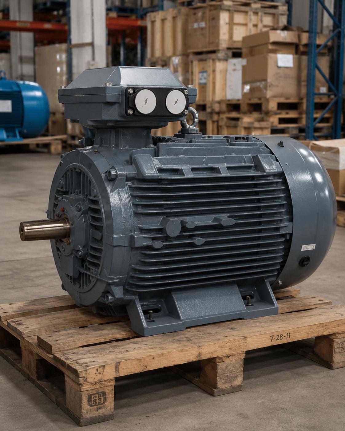
For a business investing in a high-efficiency motor like the IE4, monitoring its temperature rather than running it blindly is highly sensible; because the life of the winding insulation depends directly on temperature, and every sustained 8-10 degree exceedance roughly halves insulation life. At HEM Motor we offer IE4 motors with the Pt100 option, with winding and bearing sensors fitted at the factory, from stock and with fast delivery; this article is a guide to clarifying the right sensor configuration before ordering.
What Is a Pt100 (RTD) and Why Is It Preferred?
A Pt100 is a platinum-based resistance temperature detector (RTD). The "100" in its name means its resistance is exactly 100 ohms at 0 degrees Celsius. As temperature rises, the resistance of the platinum wire increases in a predictable, near-linear way; a monitoring relay or PLC measures this resistance and computes the temperature. The greatest strength of the Pt100 is its high accuracy and repeatability over a wide range, which is why it has become the standard in industrial motor monitoring.
| Temperature (°C) | Pt100 Resistance (ohm) | Typical Meaning |
|---|---|---|
| 0 | 100.00 | Reference point |
| 25 | 109.73 | Ambient / stopped |
| 100 | 138.51 | Normal operation |
| 130 | 149.83 | Class B limit zone |
| 155 | 159.19 | Class F limit |
| 180 | 168.48 | Class H limit |
As the table shows, the relationship between resistance and temperature is clear, and the monitoring device uses this curve to display winding temperature in degrees. This lets the operator see in real time how hot the motor has become on a gauge; far more valuable data than mere "tripped / not tripped" information.
2, 3 and 4-Wire Connection: Why Does Lead Resistance Matter?
There is a subtlety in Pt100 measurement: the cables connecting the sensor to the monitoring device also have resistance, and this lead resistance is added to the measured sensor resistance, making the temperature read higher than it really is. The longer the cable, the larger the error. To solve this, the Pt100 is offered in three connection forms:
- 2-wire: The simplest connection; lead resistance is added directly to the measurement, with no compensation. Used on short cables and where low accuracy is acceptable; generally inadequate for motor monitoring.
- 3-wire: The most common industrial standard. The third wire serves to measure and compensate the lead resistance; assuming both legs have equal cable resistance, it largely eliminates the error. This is the preferred connection for motor winding and bearing monitoring.
- 4-wire: The highest accuracy; current and voltage wires are separate, fully excluding lead resistance from the measurement. Used in laboratory and very precise applications.
In practice, IE4 motor winding and bearing Pt100 sensors are almost always wired in 3-wire form; this is the most sensible balance between accuracy and wiring cost. When selecting a monitoring relay or PLC input card, make sure it supports a 3-wire Pt100 input. Using a shielded cable from the sensor to the panel reduces electrical noise in drive-fed systems and improves reading stability.
How Many Sensors and Where?
In a standard motor monitoring configuration, Pt100 sensors are placed in two critical zones: the winding and the bearings. In the winding, typically 3 Pt100 sensors are embedded in the winding end region, one per phase, so the hottest phase temperature is captured. In the bearings, typically one each at the drive end (DE) and non-drive end (NDE), a total of 2 Pt100 sensors, are placed in the bearing seats.
| Placement | Typical Count | Risk Monitored | Typical Alarm / Trip (Class F) |
|---|---|---|---|
| Winding (per phase) | 3 Pt100 | Overload, phase imbalance, loss of cooling | Alarm ~140°C / Trip ~155°C |
| Drive-end bearing (DE) | 1 Pt100 | Lubrication failure, overload, misalignment | Alarm ~85°C / Trip ~95°C |
| Non-drive-end bearing (NDE) | 1 Pt100 | Lubrication failure, bearing current, wear | Alarm ~85°C / Trip ~95°C |
This configuration (3 winding + 2 bearing Pt100) is a common standard on large and critical IE4 motors. On smaller powers, 3 winding Pt100 alone may suffice; on very critical applications, dual (redundant) Pt100 can be added to the bearings. What matters is clearly stating at the order stage how many sensors, where, and with which connection type are required; because the sensors are placed at the factory, while the winding is being wound and the bearing seat is machined.
Terminal Box and Connection
The leads of the Pt100 sensors are brought to a small auxiliary terminal box separate from the motor's main power terminal box, or to a partitioned compartment within the main box. Keeping power cables and signal cables separate is important for both safety and reading stability; a thin Pt100 signal running right beside a high-voltage power line can produce false readings due to interference. The IP protection class of the auxiliary terminal box should be at least as high as the motor body; especially in dusty and humid environments, water or dust ingress here will disrupt the sensor connection.
Setting Alarm and Trip Thresholds Correctly
The real value of Pt100 monitoring is that it allows a two-stage protection: first alarm, then trip. The alarm threshold warns when the motor reaches a temperature that is not yet dangerous but warrants attention; at this point the operator can reduce the load, check the cooling, or plan maintenance. The trip threshold then stops the motor at the point where temperature seriously threatens insulation life, preventing burnout. This two-stage structure provides far more flexible and foresighted operation than single-threshold PTC protection.
Thresholds are set according to the insulation class. With F-class insulation, a winding alarm is typically set around 140 degrees Celsius and a trip around 155 degrees; with H-class these values can be raised somewhat. However, many operators use H-class insulation at F-class temperatures to extend life; in that case the thresholds are kept more conservative and the thermal margin increases. What matters is setting the thresholds not randomly but with regard to the motor's insulation class and operating conditions. A wrong (too high) threshold provides no protection; a wrong (too low) threshold causes unnecessary stoppages.
Of the three winding Pt100s, the monitoring device usually takes the highest value as the basis, because the real risk concentrates in the hottest phase. A phase current imbalance that occurs at partial load, or one phase being loaded differently from the others, creates a temperature difference between phases, and capturing this is only possible with a separate sensor on each phase. For this reason, choosing three winding Pt100s rather than a single one lets you see local overheating caused by imbalance.
The Difference Between Pt100 and PTC Thermistor
A common dilemma in motor thermal protection is whether to use a Pt100 or a PTC thermistor. The two serve different purposes and often complement each other:
- PTC thermistor: Its resistance rises sharply at a specific threshold temperature; the monitoring device sees this and cuts the circuit. It is a cheap, simple and reliable trip protection, but it does not display temperature in degrees; it only says "threshold exceeded."
- Pt100 (RTD): Provides continuous, linear measurement; reads temperature in degrees, allowing separate alarm and trip thresholds and trend monitoring.
The ideal approach is often to use both together: continuous monitoring and early alarm with the Pt100, and an independent, fast final trip protection with the PTC. This combination provides both predictive maintenance data and redundant safety. Depending on budget and application criticality, just one may be chosen; for example, while PTC suffices on a small IE4 motor, Pt100 monitoring is essential on a critical process motor.
Choosing the Right Sensor
The right choice becomes clear by answering a few questions. How critical is the motor? If its stoppage halts production, the investment in continuous Pt100 monitoring quickly pays for itself. Does the motor run on a drive? In drive-fed systems cooling weakens at low speed and the winding heats faster; here Pt100 monitoring is even more valuable. What is the insulation class? Alarm and trip thresholds are set according to F or H class insulation. Is there a monitoring relay or a PLC/SCADA on the panel side? The sensor output and connection type are determined accordingly.
- Critical, large-power IE4 motor: 3 winding + 2 bearing Pt100, 3-wire, supported by PTC.
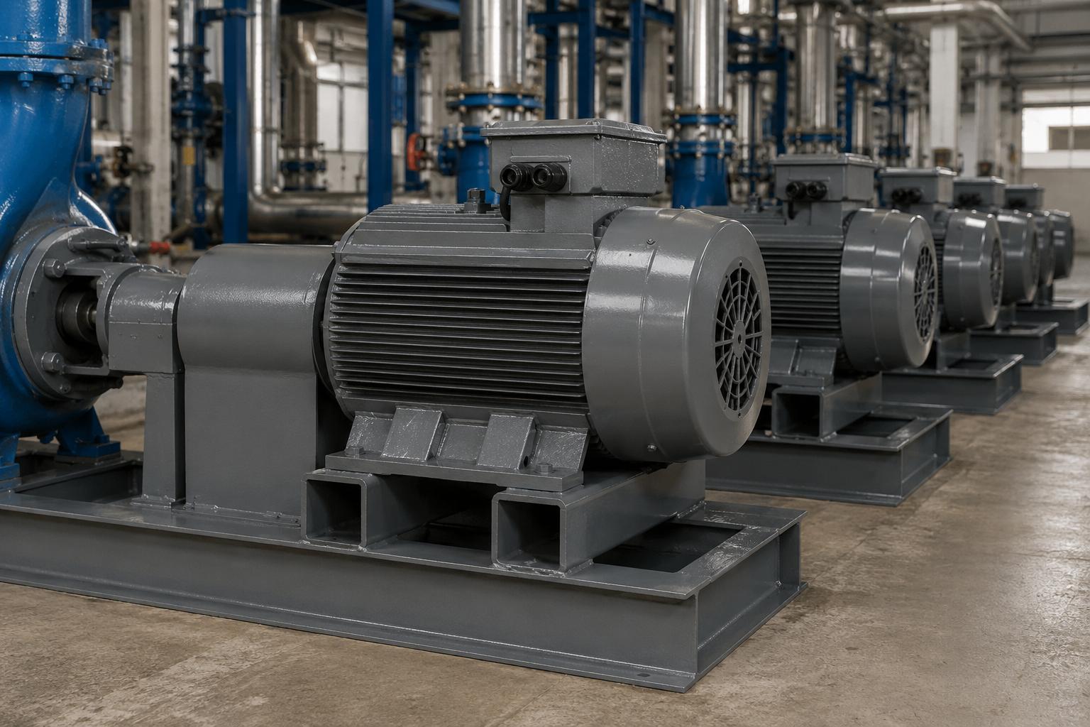
- Drive-fed (VFD) application: Pt100 monitoring + shielded cable; heating risk is high at low speed.
- Small-power, less critical motor: PTC may suffice; Pt100 optional per budget.
- High humidity/dust: high IP protection required on the auxiliary terminal box.
Temperature monitoring forms a whole with the motor's other protections; the thermal relay, the thermal relay, the motor protection circuit breaker (MPCB) and phase protection complement the Pt100. A well-designed protection chain lets you preserve the efficiency advantage of the IE4 motor for many years.
Frequently Asked Questions
What happens if I use a 2-wire Pt100 instead of a 3-wire?
In a 2-wire connection the cable resistance is added directly to the measurement, making the temperature read higher than it is. The difference is small on short cables, but if there is a long distance from the motor to the panel, the error can reach a few degrees; this misleads the alarm and trip thresholds. The 3-wire connection is the standard in motor monitoring and largely eliminates this error at the cost of a single extra wire.
Can I have Pt100 sensors added to the motor later?
Because winding Pt100s are placed while the winding is being wound, and bearing Pt100s while the bearing is machined, adding them later practically requires dismantling the motor and is usually not economical. The best approach is to state the need at the order stage and request the motor with sensors from the factory. That is why clarifying the sensor configuration before purchase is critical.
Why is the bearing Pt100 alarm threshold lower than the winding's?
Because the permissible operating temperature of bearings is lower than the endurance of the winding insulation; bearing grease and steel surfaces typically warn around 90-95 degrees Celsius. While the winding withstands up to 155 degrees with F-class insulation, the bearing must alarm much earlier. That is why separate thresholds are defined for the two zones.
Let us determine the right Pt100 configuration for your IE4 motor together. Share with us how many sensors, where, with which connection type and to which monitoring system they will connect; request a quote for IE4 motors from HEM Motor stock with winding and bearing Pt100 sensors fitted at the factory, with fast delivery and a correct configuration recommendation. The path to making an efficient motor long-lived runs through being able to see its temperature continuously.