English
 Türkçe
When you buy an IE4 motor, half the job is done; the other half is setting up the panel that feeds it correctly. The matched selection of the fuse, contactor and thermal overload relay that protect the motor is called protection coordination. A poorly coordinated panel can weld the contactor in a short circuit, destroy the thermal relay or, worst of all, clear the fault too late and burn the motor and cable. Because the starting current and efficiency curve of IE4 motors differ from standard motors, this coordination becomes even more critical. In this article we explain the difference between Type 1 and Type 2 protection, what short-circuit coordination means, and which information to request along with the panel for correct supply, all from a purchasing focus.
What Is Protection Coordination?
A motor circuit has three core protection elements: the fuse or motor protection circuit breaker that protects against short circuits, the contactor that starts and stops the motor, and the thermal overload relay that protects against overload. These three work as a team, not in isolation. Coordination ensures that during a fault each element trips in the right order and at the right time. Under overload the thermal relay opens first; the contactor breaks the circuit; in a very large short circuit the fuse clears the circuit instantly. If this hierarchy is broken, the weakest link in the chain gets damaged.
Thanks to their high efficiency, IE4 motors run with lower losses than a standard motor of the same power; however, the inrush current drawn at start-up can be high. The fuse must therefore be large enough not to nuisance-trip on inrush, yet sensitive enough to clear a short circuit quickly. The thermal relay must be set to the motor's true rated current; the current value on the nameplate is the basis here. Our guide on rated current and cable, fuse and contactor selection in IE3 motors follows the same logic for IE4.
Roles of the Circuit Elements
- Fuse / motor protection breaker: Instantly clears short circuits and very high currents.
- Contactor: Switches the motor on and off in normal operation; isolates the circuit after a fault.
- Thermal relay: Detects sustained overload and trips before the winding burns.
- Motor protection breaker (MPCB): In some panels combines fuse and thermal functions in one device.
The Difference Between Type 1 and Type 2 Protection
Short-circuit coordination is divided into two classes in the international standard. Type 1 protection allows the contactor and thermal relay to be damaged after a short circuit; the only requirement is that no external danger arises and people are not harmed. The fault is cleared, but the elements may have to be replaced. Type 2 protection is a much higher target: after a short circuit the contactor and thermal relay must remain usable apart from minor contact welding, and the circuit must be restartable.
Which one you choose depends on how critical the application is. Where downtime is very expensive and the production line must not stop, Type 2 coordination is preferred, because operation can continue after a fault without replacing elements. Type 2 coordination is guaranteed only with a fuse + contactor + thermal trio tested together in the same manufacturer's compatibility tables. Randomly chosen elements do not provide Type 2. For this reason, stating "I want Type 2 coordination" at panel supply ensures the correct combination is selected.
Which Protection for Which Case?
- Type 1 — low criticality: Applications where a short stop after a fault is acceptable and spare elements are on hand.
- Type 2 — high criticality: Continuous production, expensive downtime, hard-to-access panels; expectation of uninterrupted continuation after a fault.
- Short-circuit current (Icc): The prospective short-circuit current fed from the plant transformer defines the breaking capacity of the elements.
Starting Current and Fuse Selection in IE4 Motors
The starting behaviour of IE4 motors is the most sensitive point of coordination. The high-efficiency winding design can draw a high peak current at start-up. In high-power direct-on-line (DOL) starts this current reaches several times the rated current. The fuse must not trip on this transient current; yet it must open within milliseconds during a real short circuit. This balance is achieved with gG/gM or aM type fuses designed for motor applications, or with an adjustable motor protection breaker.
When a soft starter or variable frequency drive (VFD) is used, the starting current drops and coordination becomes easier; but this time the drive's input protection must also be included in the coordination. On generator-fed sites the starting current can strain the generator; in that case our article on motor selection on generator-powered sites explains the starting current problem and its solutions.
Points to Watch in Fuse and Thermal Setting
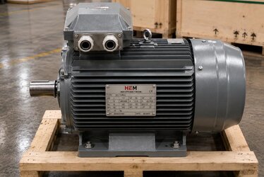
- Take rated current from the nameplate: The thermal relay is set to this value, not by guesswork.
- State the starting method: DOL, star-delta, soft starter or VFD changes the coordination.
- Fuse type: Choose a gG/gM/aM characteristic suited to the motor application.
- Breaking capacity: Must exceed the plant's prospective short-circuit current.
- Service factor: The SF stated on the nameplate affects the thermal setting margin.
Correct Motor and Panel Supply
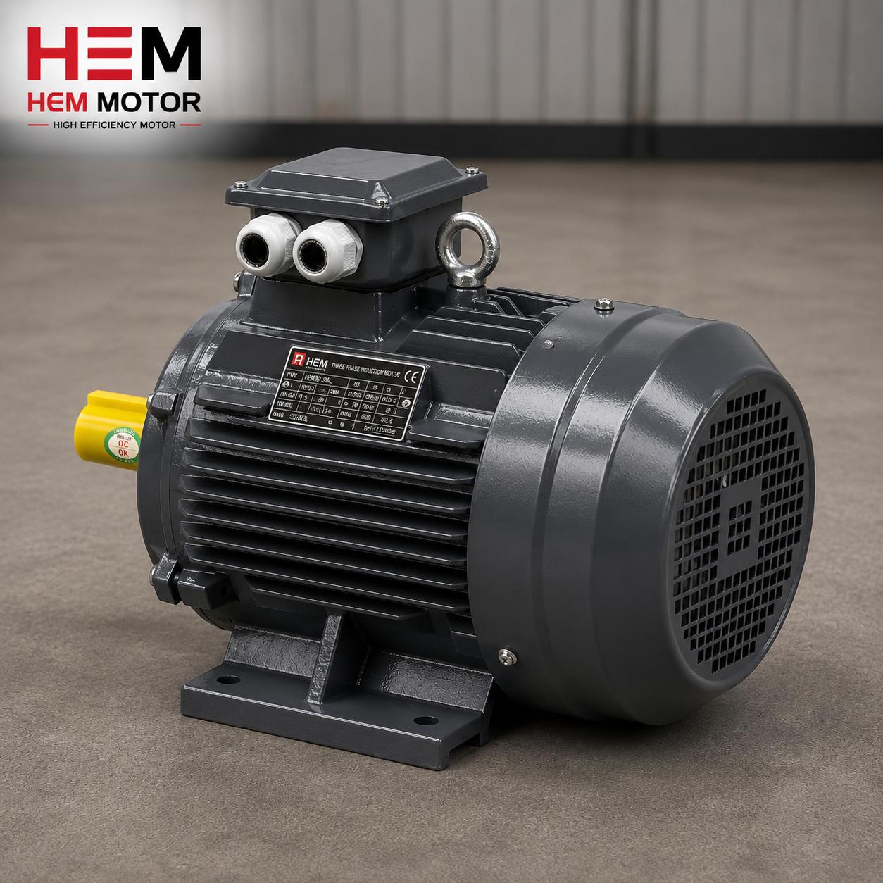
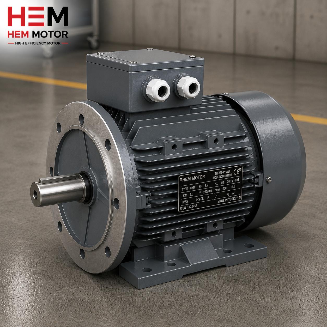
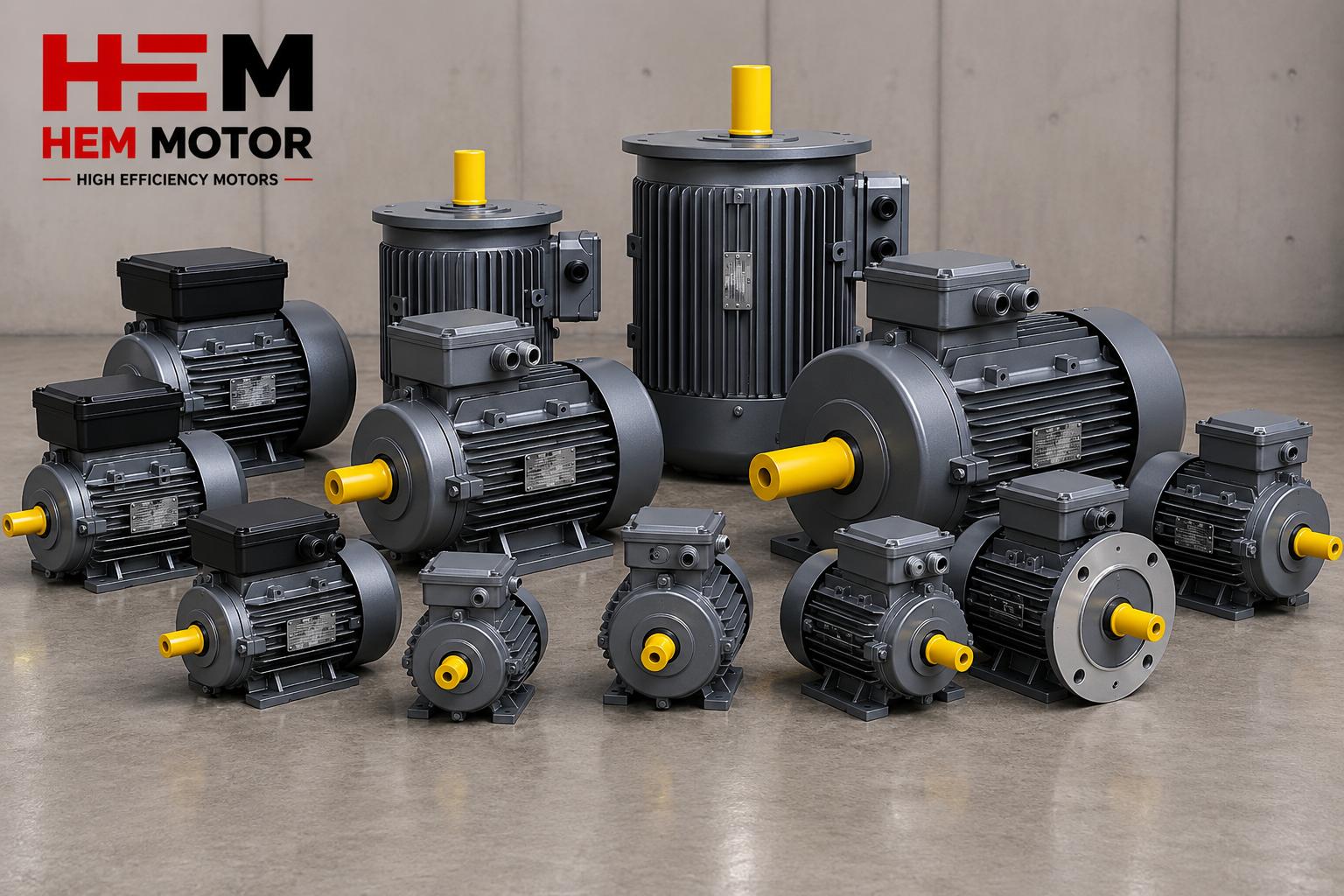
Sound coordination begins with ordering the right motor with the right information. The HEM Motor range offers IE4 super premium motors from 0.25 kW to 355 kW with IP55 protection and class F insulation; the nameplate current values and starting characteristics are clear so you can set up panel coordination correctly. At the quotation stage, stating the motor's power, speed, starting method and the desired protection type (Type 1 / Type 2) ensures both the motor and the panel elements are selected to match. To request a quote with current electric motor prices and stock status, providing this information speeds up the process.
Our article on purchasing electric motor protection devices covers the advantages of supplying protection gear together with the motor and helps you set up the fuse-contactor-thermal trio correctly from the start. Correct coordination protects not just the motor but the entire feeder and prevents unexpected downtime.
Information to Request at Supply
- Motor rated current and power: Determines the thermal and contactor size.
- Starting method: DOL / star-delta / soft starter / VFD.
- Desired protection type: Type 1 or Type 2, by application criticality.
- Plant short-circuit current: The key data defining breaking capacity.
Correct Sizing of the Contactor and Thermal Relay
The heart of coordination is the correct sizing of the contactor and thermal relay according to the motor's real current. The contactor is chosen in a category able to carry the motor's rated current continuously and to withstand the high current during starting. The contactor category designed for motor applications prevents the contacts welding even under frequent switching and high starting current. A contactor chosen in the wrong category produces contact wear and failure within months.
The setting range of the thermal relay must also suit the motor. The relay is chosen so the motor's rated current falls in the middle of the setting range; if the current value falls at the end of the range, fine adjustment becomes difficult. The thermal relay setting is made according to the current value on the motor nameplate, and the service factor is taken into account. A correctly set thermal relay protects the motor in overload while not nuisance-tripping on a normal start; this balance is critical for production continuity.
The contactor and thermal relay working together define the daily operation of coordination. In overload the thermal relay trips and de-energises the contactor coil to open the circuit; in a short circuit the fuse or breaker steps in. A clear division of this duty ensures each element works within its own limits and no element has to take over the job of another. Correct sizing is the foundation of this division working smoothly.
Coordination by Starting Method
How coordination is set up depends directly on how the motor starts. Direct-on-line (DOL) is the simplest method but draws the highest starting current; so it is the toughest scenario for fuse and contactor selection. Star-delta starting lowers the starting current but requires two contactors and a timer relay; in this case coordination is built on a more complex circuit instead of three elements. Power and application determine which method is needed.
A soft starter and a variable frequency drive (VFD) protect both the motor and the mains by smoothing the starting current. When these devices are used, the classic contactor-thermal logic gives way to electronic protection; but a suitable fuse or breaker is still needed for short-circuit protection. In VFD systems the drive's own input protection must be coordinated with the upstream fuse. Stating the starting method at order stage ensures the panel is set up correctly from the start and prevents costly later revisions.
Starting Methods and Their Coordination Effect
- DOL (direct): Highest starting current; fuse and contactor are chosen most carefully.
- Star-delta: Lower starting current; two contactors and a timer relay enter coordination.
- Soft starter: Smooth start; mechanical and electrical strain is reduced.
- VFD: Lowest starting current; drive input protection is matched to the upstream fuse.
Common Coordination Mistakes
The most common field mistake is selecting elements one by one with "seemingly sufficient" values without testing them together. Even when the right fuse, right contactor and right thermal are each chosen individually, it is not guaranteed they provide Type 2 coordination together; this is verified only with the manufacturer's compatibility table. The second common mistake is setting the thermal relay to an estimated value instead of the nameplate rated current; this either leaves the motor unprotected in overload or trips needlessly and stops production.
A third mistake is the fuse breaking capacity falling below the plant's prospective short-circuit current. Such a fuse can explode in a large short circuit and cause damage. So the short-circuit current fed from the plant transformer is the basic data of element selection. All these mistakes are prevented by a supply approach that evaluates the motor and panel elements together with the right information.
Frequently Asked Questions
What is the practical difference between Type 1 and Type 2 coordination?
In Type 1 the contactor and thermal relay may be damaged after a short circuit; the fault is cleared but the elements may be replaced. In Type 2 these elements remain usable after a short circuit and the circuit can be restarted. Type 2 is preferred for continuous production and expensive downtime, Type 1 where a short stop is acceptable.
Will the IE4 motor's starting current trip the fuse?
Not if the right fuse is chosen. gG/gM or aM type fuses suited to motor applications withstand the transient inrush while clearing a real short circuit quickly. If a small or domestic fuse is chosen by mistake, it may trip on every start. Using a soft starter or VFD lowers the starting current and reduces this risk.
To what value should I set the thermal relay?
The thermal relay is set to the motor's rated current; this value is written on the motor nameplate. An estimated value should not be used; the nameplate current is the basis. Service factor and ambient temperature can affect the setting margin, so sharing nameplate information at order stage ensures correct protection.