English
 Türkçe
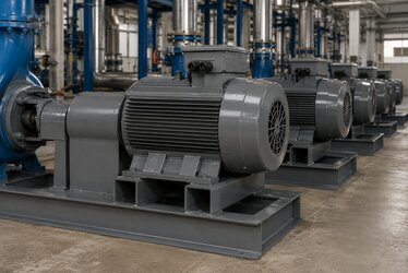
IE5 synchronous reluctance (SynRM) motors — with their magnet-free rotor, high efficiency and drive-coupled operation — represent the ultra premium efficiency class of the future. One of the most important predictive-maintenance indicators for reliable, long-life operation of these motors is the vibration level. But for a vibration measurement to be meaningful you need a baseline: the reference vibration recorded while the motor is healthy is the comparison point for all subsequent field measurements. The ISO 20816 standard provides the framework for establishing this baseline, performing acceptance measurements and classifying vibration zones (A/B/C/D).
In this article we cover how to take the vibration baseline on an IE5 synchronous reluctance motor, the ISO 20816 zone A/B/C/D definitions and mm/s rms limits, factory acceptance measurement, field trending with predictive maintenance, and the subtleties of measuring vibration under drive operation. The goal is to help you set the correct acceptance criterion and confidently manage your motor's vibration history.
Why Is the Vibration Baseline Important?
The baseline is the reference vibration measurement taken while the motor is new or freshly overhauled and in a healthy state, under normal load, speed and mounting conditions. This is the foundation of predictive maintenance: whether a motor is "high" in vibration is not meaningful on its own; what matters is the change relative to its own baseline (trend). A motor running at 1.8 mm/s may be healthy; but a motor whose baseline was 0.8 mm/s that has risen to 1.8 mm/s is signalling a developing fault (unbalance, bearing wear, alignment drift).
For this reason every IE5 motor, when commissioned, should ideally have its baseline recorded at commissioning; the measurement points (bearing housings, horizontal/vertical/axial directions) marked, and periodic measurements taken from the same points. ISO 20816 defines both the method of this measurement and the absolute evaluation zones.
ISO 20816 Zones: A, B, C, D
ISO 20816 (the series replacing the former ISO 10816) evaluates machine vibration via broadband vibration velocity (mm/s rms) and defines four zones:
- Zone A: A newly commissioned healthy machine. Vibration is low; the target zone for acceptance.
- Zone B: A machine considered acceptable for unrestricted long-term operation. The normal operating zone in most applications.
- Zone C: Not satisfactory for long-term continuous operation; can run for a limited time, corrective maintenance should be planned.
- Zone D: Vibration of a severity that may cause damage. The machine must be stopped and the root cause found.
The table below summarises typical zone limits in mm/s rms for rigid and flexible-foundation machines by IEC frame size. These values are a general reference based on ISO 20816-1/-3; exact classification is made by machine group and foundation type.
| Zone Limit | Small machine (rigid) mm/s rms | Medium-large machine (flexible) mm/s rms | Evaluation |
|---|---|---|---|
| A/B boundary | ≤ 1.4 | ≤ 2.3 | New/acceptance |
| B/C boundary | ≤ 2.8 | ≤ 4.5 | Operating upper limit |
| C/D boundary | ≤ 4.5 | ≤ 7.1 | Warning / alarm |
| Zone D | > 4.5 | > 7.1 | Stop / investigate |
As the table shows, machine size and foundation rigidity change the limits. In IE5 motor acceptance measurement, the column matching the motor's group and mounting type must be used.
Factory Acceptance Measurement
A quality IE5 motor is subjected to a vibration measurement while running free (no-load) at the factory and reported. The acceptance criterion generally targets "zone A or upper B." Points to watch in the factory acceptance test: taking the measurement from the bearing housing, treating the motor as flexible/rigid, using a calibrated instrument and reporting in mm/s rms. For details on how vibration is measured in incoming acceptance inspection, our article on incoming and acceptance inspection provides guidance.
If you want to review the relationship between vibration/balance acceptance values and quality, our article on vibration and balance ISO acceptance values provides the foundation. Our article on IE4 vibration and balance (ISO 20816) offers a comparison for super premium motors.

Field Trending and Predictive Maintenance
While absolute zone evaluation (A/B/C/D) matters, the real power of predictive maintenance lies in trend analysis. After the baseline is recorded, measurements are taken at regular intervals (e.g. monthly) from the same points and the change over time is tracked. A rising trend can indicate a developing fault even while the absolute value is still within zone B.
- Unbalance: dominant vibration increase at 1× running frequency.
- Misalignment: increase at 2× frequency and in the axial direction.
- Bearing fault: indication in high-frequency bands, in envelope analysis.
- Looseness: irregular increase in harmonics and broadband.
Looking at the frequency spectrum lets you distinguish which type of fault is developing. For bearing-related problems, our article on shaft grounding and bearing current on IE5 addresses bearing protection under drive operation.
Vibration Under Drive (VFD) Operation
The IE5 synchronous reluctance motor inherently runs with a drive. There are points to watch when measuring vibration under drive operation: vibration changes with variable speed, so the baseline and acceptance measurement must be taken at a defined reference speed and load. Drive switching harmonics can add electrical noise to the measurement; in mechanical vibration measurement the accelerometer must be correctly filtered. Resonance (critical speed) can also appear at certain speeds; a "skip frequency" can be defined in the drive to avoid these speeds.
The effect of voltage spikes reaching the motor on the winding insulation under drive operation is a separate topic; our article on IE5 output sine filter and du/dt is complementary.
How to Set the Correct Acceptance Criterion?
If you want to set a clear criterion for vibration when ordering an IE5 motor, specify: the target zone (generally "≤ upper zone B limit, preferably zone A"), the reference speed and load, the measurement points, and a request for the factory vibration report. This both confirms quality at delivery and forms the basis for the field baseline.
Measurement Points and Correct Method
For the vibration measurement to be repeatable, the measurement points must be standardised. ISO 20816 recommends taking the measurement from the machine's bearing housings. Three directions are measured at each bearing: horizontal (H), vertical (V) and axial (A). The horizontal direction usually gives the highest value (frame rigidity is lower horizontally); the axial direction catches alignment and angular-misalignment problems.
- Mark the measurement points permanently with paint or a label; measure from the same point every time.
- Couple the accelerometer to the surface with a firm magnetic or stud mount; hand-holding causes errors at high frequency.
- Take the measurement at steady load and speed, not in a transient regime.
- Record the broadband mm/s rms value and, if possible, the spectrum.
Separating the measurement into horizontal/vertical/axial lets you distinguish the fault type (unbalance, misalignment, looseness) instead of simply saying "vibration is high." That means correct and timely intervention.
Sources of Vibration: Mechanical or Electrical?
On an IE5 synchronous reluctance motor, vibration can be of both mechanical and electrical origin. Mechanical sources are unbalance, misalignment, bearing wear, loose bolts and weak foundations. Electromagnetic sources are rotor-stator air gap irregularity, drive switching effects and magnetic force ripple. A practical way to separate the two is to decouple the motor from the drive and observe vibration during coast-down: if vibration drops immediately when power is cut it is electrical; if it falls gradually with speed it is mechanical. This distinction is critical for the correct maintenance decision.
Vibration Velocity, Acceleration and Displacement: Which to Measure?
Vibration can be expressed by three different quantities: displacement (µm), velocity (mm/s) and acceleration (g or m/s²). Each carries information in a different frequency band, and choosing the right parameter makes the evaluation meaningful:
- Displacement (µm): meaningful for low-frequency (low-speed) events and shaft movement. Generally used for relative shaft vibration at bearings.
- Velocity (mm/s rms): the most balanced indicator in the mid-frequency band (general machine vibration); ISO 20816 makes its broadband evaluation via this quantity. Unbalance, misalignment and looseness appear in this band.
- Acceleration (g): dominant in high-frequency events (bearing defects, gears, electromagnetic). Acceleration/envelope analysis is used for early bearing-fault diagnosis.
While the IE5 motor's general acceptance evaluation is made via mm/s rms velocity, acceleration-based envelope analysis is added for bearing predictive maintenance. The two methods complement each other: velocity gives general health, acceleration gives early bearing indication.
Resonance and Critical Speed
Every mechanical structure has a natural frequency. When the motor's rotational frequency (or a harmonic of it) approaches this natural frequency, resonance occurs and vibration increases greatly. On a drive-driven IE5 synchronous reluctance motor, since speed varies over a wide range, resonance can be entered at certain speeds. These speeds are called critical speeds.
Practical ways to manage resonance are: identifying the critical-speed speeds with a coast-down or run-up/run-down test; defining a "skip frequency" band in the drive to avoid continuous operation at these speeds; and raising the foundation rigidity to move the natural frequency outside the operating band. Resonance should not be confused with the baseline: high vibration at resonance is not a fault but a design/operation matter; however, running continuously at resonance fatigues the bearing and winding.
The Effect of Mounting and Foundation on Vibration
The measured vibration reflects not only the motor's own condition but also the mounting quality. Loose foot bolts, an uneven foundation, soft foot and poor alignment make even a healthy motor read high vibration. So before taking the baseline:
- Verify that all foot bolts are tightened to the correct torque.
- Perform a soft-foot check; shim if necessary.
- Correct the motor-load alignment (coupling) with laser alignment.
- Make sure the foundation is rigid and flat.
Good mounting means both a low baseline and reliable trend tracking. Otherwise, mounting-related vibration can mask a developing fault or produce a false alarm. For the effect of shaft radial/axial load and alignment on bearing life, our article on shaft radial and axial load limit provides guidance.
Frequently Asked Questions
Should I use ISO 10816 or ISO 20816?
The ISO 20816 series is the current standard that replaces the ISO 10816 and ISO 7919 series and unifies the vibration measurement/evaluation framework. New acceptance measurements should be based on ISO 20816. When comparing with older measurements, since the zone limits are largely similar, trend tracking remains meaningful.
When should I take the baseline?
The baseline should be taken when the motor is newly commissioned or after a major overhaul/bearing replacement, running healthily at normal load and speed. The measurement points must be marked and all subsequent periodic measurements taken from the same points at the same reference speed/load; only then is the trend meaningful.
Why does vibration read differently under drive operation?
The vibration level changes with variable speed and resonance (critical speed) can cause an increase at certain speeds. So the baseline and acceptance measurement must be taken at a fixed reference speed and load, and resonance speeds identified and skipped in the drive. Switching harmonics can also add electrical noise; the measurement must be correctly filtered.
At HEM Motor we supply IE5 synchronous reluctance ultra premium motors with a factory vibration acceptance report, ISO 20816-based quality control and drive-compatible construction — from stock and with fast delivery. Send us your target vibration zone, reference speed and application details; request a quote for the right acceptance criterion and motor selection, and let us build your predictive-maintenance infrastructure together.