English
 Türkçe
When you want to bolt an IE3 motor to a pump, a gearbox or a machine, the success of the installation is decided as much by the flange type and dimensions as by the construction type (foot-mounted B3, flanged B5 or flanged B14). One of the most common problems in the field is that the ordered motor's flange bolt circle (pilot diameter) or hole type (clearance or tapped) does not match the machine it will connect to. In this article we cover in detail the difference between FF (clearance) and FT (tapped) flanges on IE3 motors, the distinction between the B5 large flange and the B14 small flange, the concepts of flange diameter, bolt circle and pilot (spigot) diameter, mounting compatibility, special flange needs, and correct flange selection when connecting to a pump or gearbox. At HEM Motor our goal is to help you choose a flange that is fully compatible in dimensions and hole type with the machine you will connect the motor to.
What Is a Flanged Motor? The Basic B5 vs B14 Distinction
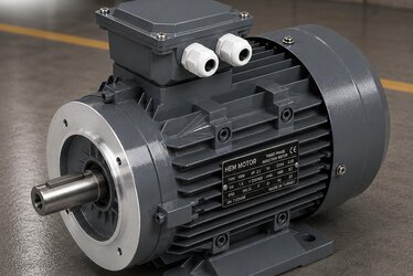
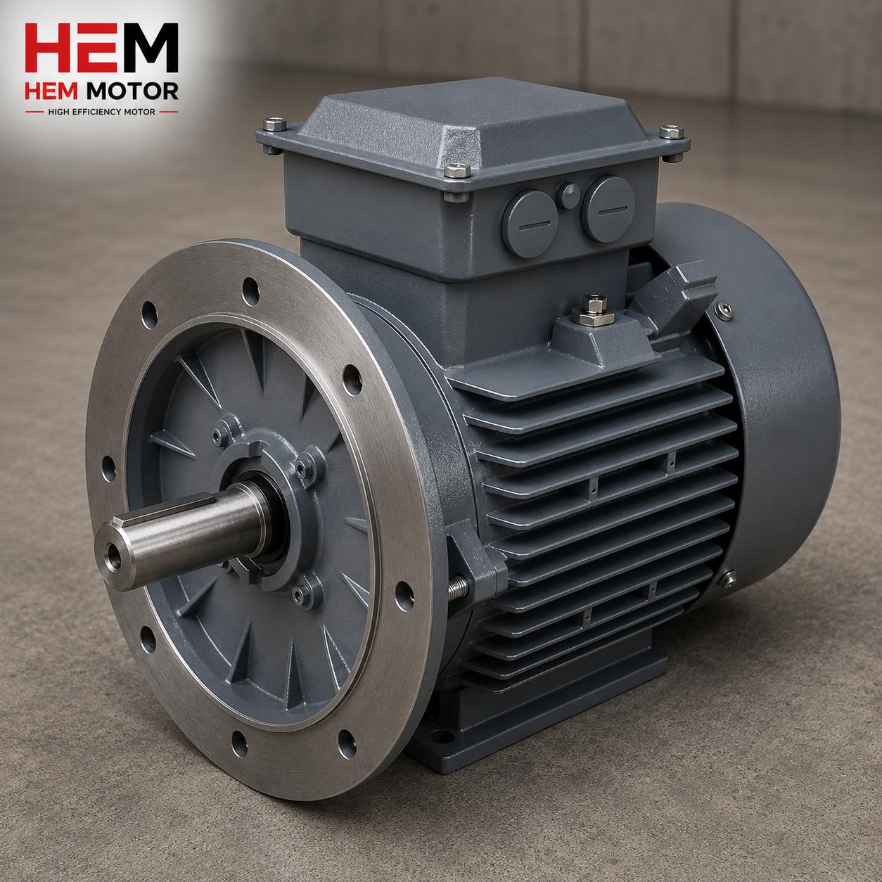
A flanged motor has a circular mounting flange on the drive-end shield where the shaft exits. Thanks to this flange the motor is bolted directly to a machine, gearbox or pump housing without the need for feet. The IEC standard has two basic flange families:
- B5 (large flange, FF type): The flange is a large-diameter plate extending beyond the motor body, with clearance holes. The bolt passes from behind the flange and fastens to a tapped hole or nut on the machine side. It is generally used on gearboxes and large machines.
- B14 (small flange, FT type): A smaller-diameter flange close to the motor, with tapped holes. The bolt passes from the machine side and screws into the flange's tapped hole. It is generally used on pumps and compact machines.
These two types differ in both dimensions and hole logic. If you order the wrong type the bolts will not seat, so you must clarify the flange interface of the part you will connect to from the outset. To code the mounting position correctly, our article on reading the IM mounting code (IM B3, IM B5, IM V1) is a fundamental resource.
The FF (Clearance) vs FT (Tapped) Flange Difference
In the IEC 60072 standard, flange types are defined by the abbreviations FF and FT. These two letters define the hole type and therefore which direction the bolt fastens from:
- FF (Flange, clearance holes): The flange has plain, unthreaded clearance holes. The bolt passes through the flange hole and fastens to a tapped hole or nut on the opposite side. B5 motors are typically FF-flanged.
- FT (Flange, tapped holes): The flange has tapped holes. The bolt passes from the counterpart and screws directly into the flange thread. B14 motors are typically FT-flanged.
The FF vs FT distinction is critical because it reverses the mounting direction. With an FF flange you must be able to reach the bolt from behind the flange; with an FT flange you reach it from the machine side. On closed-housing connections such as pumps, FT (B14) is usually preferred, because the bolt passes through the pump housing and screws into the motor flange. For gearbox connections, FF (B5) is generally used.
| Feature | FF Flange (B5) | FT Flange (B14) |
|---|---|---|
| Hole type | Clearance (through) | Tapped (threaded) |
| Bolt direction | Passes from behind the flange | Enters from machine side, screws into flange |
| Flange size | Large, overhanging | Small, compact |
| Typical use | Gearbox, large machine | Pump, compact machine |
| Access | Bolt from motor rear | Bolt from machine side |
Flange Dimensions: Diameter, Bolt Circle and Pilot
Three basic dimensions define a flange, and mounting compatibility depends on all three matching:
- Outer diameter (M): The outermost diameter of the flange plate.
- Bolt circle (N / pitch circle): The diameter of the circle on which the centres of the mounting holes lie. The bolt pattern is set by this diameter.
- Pilot / spigot diameter (P / rabbet): The precise protrusion or recess at the centre of the flange that seats into the machine. It centres the motor concentrically with the machine; it is critical for shaft alignment.
The IEC standard expresses each flange size with a number (for example FF115, FF130, FF165, FF215, FF265…). This number gives the bolt circle diameter (N, mm). Similarly, B14 flanges are coded as FT65, FT85, FT100, FT115, FT130. The table below summarises the typical B5 (FF) and B14 (FT) flange codes corresponding to common IEC frame sizes. For a correct replacement, the frame-shaft-flange trio must be evaluated together; on this our article on the IE3 shaft diameter and frame table (IEC 56-355) is complementary.
| Frame (IEC) | B5 Flange (FF) Code | Pilot Diameter (P) ~mm | B14 Flange (FT) Code |
|---|---|---|---|
| 71 | FF130 | 110 | FT85 |
| 80 | FF165 | 130 | FT100 |
| 90 S/L | FF165 | 130 | FT115 |
| 100 L | FF215 | 180 | FT130 |
| 112 M | FF215 | 180 | FT130 |
| 132 S/M | FF265 | 230 | FT165 |
| 160 M/L | FF300 | 250 | — |
| 180 M/L | FF300 | 250 | — |
| 200 L | FF350 | 300 | — |
The values in the table are typical IEC equivalents; they may vary by manufacturer and by custom build. So for critical installations you must always compare the motor's dimension drawing with the interface of the machine to be connected. The absence of B14 on large frames is because the small flange does not have a bolt pattern able to carry large powers; that is why B5 (FF) is standard on large motors.
Mounting Compatibility: Pilot Diameter and Shaft Alignment
The most often overlooked yet most critical dimension in a flange connection is the pilot (spigot) diameter. The pilot brings the motor shaft concentric with the machine's input shaft. If the pilot diameter does not match, even when the bolt circle fits the shaft remains offset, which means vibration, bearing wear and coupling damage. So in a flange connection the pilot diameter and its tolerance are at least as important as the bolt circle.
The shaft end is also part of the compatibility equation: the shaft diameter, shaft length and key size must match the coupling or pulley to be connected. For choosing a flexible or rigid coupling and aligning the shaft in a motor-machine connection, our article on coupling selection and shaft alignment is a practical guide. On vertical mountings (shaft down) flange and seal selection becomes additionally important; see our article on vertical mounting V1/V5.
Special Flange Needs
Standard IEC flanges cover most applications, but some machines require a special flange. For example an old machine's hole pattern may differ from standard, or a pump manufacturer may demand its own pilot diameter. In these cases there are two routes: have the motor built with a special flange, or use an adapter (intermediate) flange. The dimensions to watch on a special flange are:
- Bolt circle diameter and number of holes
- Hole diameter and type (FF clearance or FT tapped)
- Pilot diameter, depth and tolerance
- Flange outer diameter and thickness
- Shaft diameter, length and key size
At HEM Motor, alongside standard B5/B14 flanges, we also support special flange and shaft configurations suited to your machine. On the accessory and option side, our article on IE3 accessory options (brake, encoder, forced-cooling fan) gathers the points to clarify before ordering.
Correct Flange Selection for Pump and Gearbox Connections
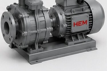
For pump connections, the B14 (FT) small flange is usually used; on centrifugal pumps the motor screws directly to the pump housing for a compact structure. For gearbox connections, the B5 (FF) large flange is mostly preferred; the gearbox input flange seats onto the motor's large plate. Since output speed and torque are also critical in monoblock geared motor selection, our article on purchasing a monoblock geared motor is a useful complement.
Common Mistakes in Flange Connections
There are a few recurring mistakes in flanged-motor installation in the field, and all of them are preventable in advance. Knowing them eliminates surprises after the motor arrives:
- Looking only at the bolt circle: Even if the bolt circle fits, if the pilot diameter differs the motor will not seat on the machine. Always check all three dimensions (outer diameter, bolt circle, pilot) together.
- Confusing FF with FT: Because the bolt direction is reversed, the wrong type cannot be connected in the field. Clarify where the machine side reaches the bolt from.
- Forgetting the shaft end: Even if the flange fits, if the shaft diameter or length does not match the coupling the connection cannot be made. Flange and shaft must be evaluated together.
- Skipping seal and sealing: On wet-environment connections such as pumps, the flatness of the flange face and the seal groove matter.
- Ignoring tolerance: The pilot diameter usually requires a tight tolerance (for example j6); a loose tolerance leads to centring error.
The common thread in these mistakes is not comparing the dimension drawing before installation. The correct method is to place the flange interface drawings of both the motor and the machine side by side and confirm the three basic dimensions and the shaft end. Our article on mistakes when buying an electric motor is also useful from this angle.
Using a Flanged and Foot-Mounted Motor Together (B35)
In some applications the motor is both foot-mounted and flanged; this combination is called B35 (IM B35). Here the motor sits on the ground via its feet and is also connected to the machine via its flange. This dual connection provides extra rigidity under large and vibrating loads. But there is one point to watch in B35 mounting: both the feet and the flange must be in the same plane; otherwise the body is strained and stress builds up. So in B35 mounting the flange is connected first, then if needed a shim plate is placed under the feet to achieve stress-free seating. B35 is frequently preferred on large pump and fan drives.
Frequently Asked Questions
What is the difference between FF and FT flanges?
On an FF flange the holes are plain and unthreaded (clearance); the bolt passes from behind the flange. On an FT flange the holes are tapped; the bolt passes from the counterpart and screws into the flange. B5 motors are generally FF-flanged, B14 motors generally FT-flanged.
Should I choose B5 or B14?
It depends on the machine you connect to. Gearboxes and large machines generally use B5 (large flange, FF), while pumps and compact machines generally use B14 (small flange, FT). Choose whichever the machine's flange interface requires.
Why is the pilot diameter important?
The pilot (spigot) diameter is the precise protrusion or recess that brings the motor shaft concentric with the machine's shaft. If the pilot does not match, even when the bolt circle fits the shaft remains offset, leading to vibration, bearing wear and coupling damage. So in flange selection the pilot diameter and its tolerance are critical.
Choose the Right IE3 Flanged Motor with HEM Motor
Correct selection of an IE3 flanged motor means making the flange type (FF/FT), the B5/B14 distinction, the bolt circle and the pilot diameter fully compatible with the machine you will connect to. At HEM Motor we offer B5 and B14 flanged IE3 motors, with special flange and shaft configurations, from stock and with fast delivery. Share the interface dimensions of the pump, gearbox or machine you will connect to with us; request a quote for a fully compatible flanged motor and complete the installation right the first time.