English
 Türkçe
In pump, fan and blower applications, the most effective way to control flow, pressure and energy consumption is to adjust the motor speed precisely. In most cases a variable frequency drive (VFD) is enough to do this; however, in applications with a narrow pressure tolerance, where closed-loop speed feedback is required, or where position/speed data is critical to the process, an encoder is added to the motor. The encoder converts the rotational speed and position of the motor shaft into a pulse signal and feeds the real speed back to the drive. This allows the drive to run in closed loop instead of open loop (sensorless vector); torque stays stable at low speed, speed deviation is corrected during sudden load changes, and precise flow control becomes possible along the entire pump/fan curve.
The most critical mechanical decision in encoder selection is the mounting type: should a hollow shaft encoder or a solid shaft encoder be used? This choice directly affects ease of installation, vibration resistance, alignment precision and long-term reliability. When HEM Motor supplies pump and fan motors with an encoder option, we recommend the correct encoder architecture for the vibration profile and shaft diameter of the application. In this article we cover hollow shaft and solid shaft encoder mounting, coupling and torque arm solutions, resolution selection, and how closed-loop speed control works in pumps and fans, step by step.
Why Is an Encoder Needed? Closed-Loop Speed Control in Pumps and Fans
Pumps and fans are loads with a quadratic (variable) torque characteristic; torque varies with the square of speed and power with the cube. For this reason, reducing speed is the key to energy savings in these applications. In most pumps and fans, sensorless vector or V/f control is sufficient. However, encoder-based closed loop stands out in the following cases:
- High torque at very low speed: In feed pumps or process fans, the drive must hold speed even at very low frequencies such as 1-2 Hz. Sensorless control is weak at estimating torque and speed in this region; the encoder closes this gap by measuring the actual speed.
- Narrow pressure/flow tolerance: In paper, food or chemical processes, constant pressure is very important. Encoder feedback minimizes speed deviation.
- Fast load change: During sudden valve opening/closing or damper movements, speed fluctuation is corrected much faster in closed loop.
- Synchronized operation: On lines where multiple fans/pumps must run at the same speed, the encoder guarantees speed matching.
This feedback loop between the drive and the encoder compares the actual motor speed with the reference speed and continuously corrects the difference. For in-depth information on speed feedback, see our article on tacho and encoder speed feedback on IE4 motors.
Hollow Shaft and Solid Shaft Encoder Mounting
There are two fundamental methods of connecting an encoder to a motor. The correct choice depends on the structure and diameter of the motor's rear shaft end (B side) and the vibration level of the application.
Hollow Shaft (Through-Hollow) Encoder
The hollow shaft encoder slides directly onto the motor's rear shaft end. To keep the encoder body from rotating, a torque arm (stator coupling) extending from the body is flexibly attached to the motor flange. No separate coupling is needed; the encoder sits directly on the shaft. Advantages:
- The axial length is very short; it takes little space behind the motor.
- Shaft-to-encoder alignment problems are minimal because the encoder clamps directly to the shaft.
- Because the torque arm compensates for small angular and axial misalignments, it is reliable in vibrating environments (pumps/fans).
- Installation is fast; field personnel can fit and remove it easily.
Solid Shaft Encoder
The solid shaft encoder has its own shaft and is connected to the motor shaft with a flexible coupling (bellows/oldham). The encoder is fixed by a separate foot/flange. Advantages and points to watch:
- Preferred in precise applications requiring high speed and high resolution.
- The coupling absorbs misalignment between the motor shaft and the encoder shaft; however, alignment error shortens coupling life.
- Mounting requires more precision; axial and radial misalignment limits must be respected.
- The axial length is longer than that of a hollow shaft.
The choice of coupling type in the shaft-machine connection also affects encoder mounting; our article on flexible vs rigid coupling selection and shaft alignment is a useful reference here.
Hollow Shaft vs Solid Shaft Encoder Comparison Table
| Criterion | Hollow Shaft | Solid Shaft |
|---|---|---|
| Connection method | Slides onto shaft + torque arm | Flexible coupling (bellows/oldham) |
| Ease of installation | High (no alignment needed) | Medium (precise alignment required) |
| Vibration resistance | High (ideal for pump/fan) | Medium (coupling can fatigue) |
| Axial length | Short | Long |
| Typical shaft size | 8-16 mm bore | 6-10 mm shaft end |
| Maximum speed | 3000-6000 rpm | 6000-12000 rpm |
| Suitable application | Pump, fan, blower, conveyor | High precision, servo, test bench |
| Removal/replacement | Practical, easy in the field | Alignment must be redone |
In applications such as pumps and fans that vibrate and usually run below 3000 rpm, the hollow shaft encoder stands out for both ease of installation and vibration resistance. We detailed the importance of selecting a low-noise, low-vibration motor in our article on noise and vibration in electric motors.
Resolution (PPR) Selection: How Much Precision Is Needed?
The resolution of an encoder is expressed in PPR (pulses per revolution). A higher PPR gives more precise speed/position data; however, the drive's input frequency limit and cable length must be taken into account. The practical selection range for pump and fan applications:
- 1024 PPR: Sufficient for standard pump/fan closed-loop speed control; the most common choice.
- 2048 PPR: For processes requiring more precise speed control and good resolution at low speed.
- 500 PPR: For simple speed feedback or high-speed (2-pole) fans, to avoid exceeding the drive frequency limit.
As resolution increases, especially at high speed, the encoder output frequency can push the limit the drive can read. Therefore the output frequency should be checked with the PPR x speed/60 calculation. In addition, the signal type (HTL/push-pull or TTL/RS422) and cable length also affect the choice; on long cables, the TTL/RS422 differential signal is more resistant to noise.
Signal Type and Cabling
- HTL (Push-Pull, 10-30V): Noise-resistant in industrial environments, suitable for short-to-medium cable distances.
- TTL/RS422 (5V differential): Preferred for long cables and high frequency; a shielded cable is essential.
- The encoder cable should be run in a separate channel from the motor power cable, and the shield should be grounded at a single point.
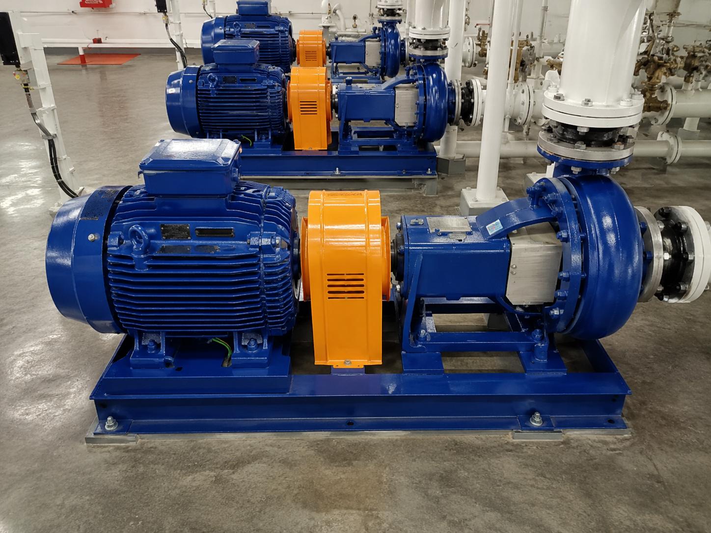
Vibration Resistance and the Pump/Fan Environment
Pump and fan motors inherently produce vibration; an unbalanced impeller, hydraulic shock, flow turbulence and belt drive increase vibration. The encoder must operate reliably in this environment:
- The hollow shaft + torque arm combination absorbs small misalignments and eliminates the risk of coupling fatigue under vibration.
- The encoder IP protection class should be selected to suit the environment; at least IP65 is recommended in dusty/humid environments.
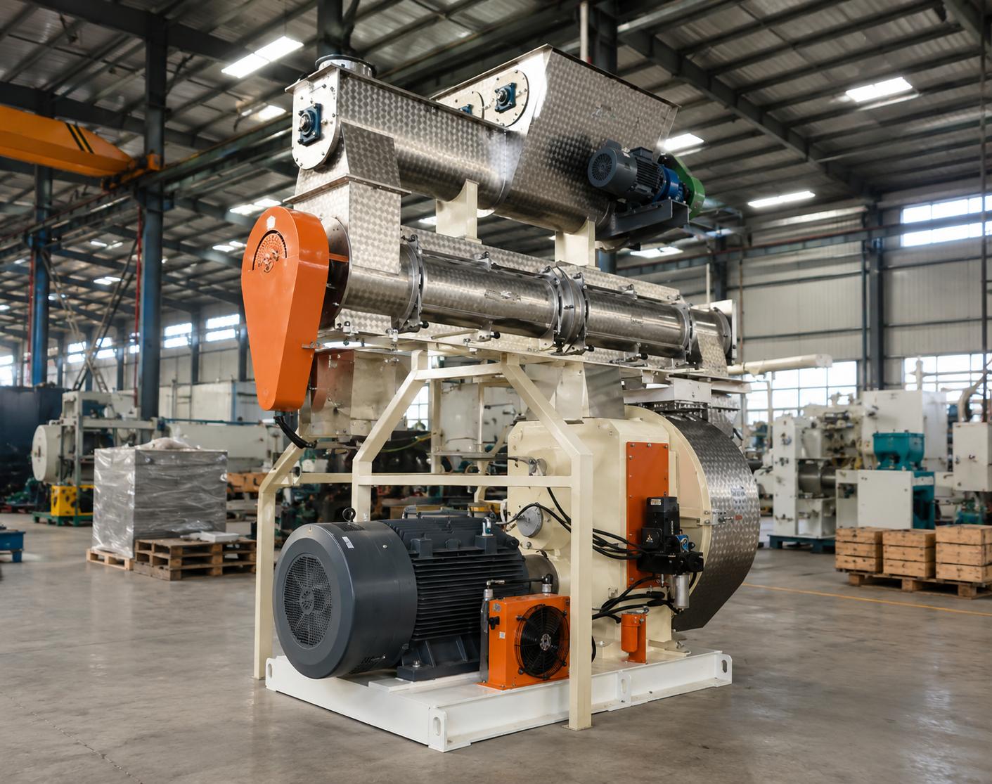
- In high-vibration crusher/heavy-duty applications, a more robust magnetic or inductive speed sensor can be considered instead of an encoder.
- Keeping bearing and shaft vibration within ISO limits extends encoder life.
Fan type selection also affects the speed control strategy; our articles on centrifugal and axial fan motor selection and centrifugal pump motor selection help you match the right motor to the application.
Correct Encoder and Motor Selection: A Practical Checklist
- Is the motor's rear shaft end (B side) suitable for an encoder? Check the bore for hollow shaft, the shaft end for solid shaft.
- If the application is vibrating, prefer hollow shaft + torque arm.
- Select the resolution according to the process; 1024 PPR is sufficient for most pump/fan cases.
- The drive's encoder card must be compatible with the signal type (HTL/TTL).
- Use an IP-rated encoder suited to the environment and a shielded cable.
- Ordering the motor from the factory with the encoder option is more reliable than field installation.
The Difference Between Open-Loop and Closed-Loop Control
A variable frequency drive can run the motor in two basic control architectures. In open-loop (sensorless) control, the drive does not measure the motor speed; it estimates it from voltage, current and frequency using a mathematical model. This method is inexpensive and sufficient for most pumps/fans. However, estimation accuracy drops at very low frequency, near-zero speed, or during sudden load impacts. In closed-loop control, the encoder measures the actual speed and feeds it back to the drive; the drive corrects the difference between the reference speed and the actual speed within milliseconds. This difference provides the following gains in particular:
- Full torque at zero speed: In encoder-based closed loop, the motor knows its position even while stationary; there is no slip in processes that must hold under load.
- Narrower speed band: While a 1-3% speed deviation is normal in open loop, this deviation drops to a far lower level in closed loop.
- Faster response: On a load change, the drive measures the speed drop and instantly increases current; pressure fluctuation is minimized.
- Safe behavior under overload: Because the actual speed is known, the drive can protect the motor without overstressing it.
The quadratic torque characteristic of pumps and fans is favorable for open loop in normal operation; however, as the process precision requirement increases, encoder-based closed loop comes into play. When making this decision, the operating speed range and load profile of the motor must be clarified.
The Most Common Mistakes in Encoder Mounting
In field applications, most encoder failures stem not from the encoder itself but from incorrect mounting and cabling. The most common mistakes are:
- Alignment error (solid shaft): If the misalignment between the motor shaft and the encoder shaft exceeds the manufacturer's limit, the coupling fatigues quickly and the encoder bearings are damaged. The hollow shaft design largely eliminates this risk.
- Over-rigid torque arm mounting: The torque arm of a hollow shaft encoder must be attached flexibly to absorb small movements. If fixed too tightly, vibration is transmitted directly to the encoder body and the body can crack.
- Running power and signal cables in the same channel: When the encoder signal cable runs parallel to the motor power cable over a long distance, electromagnetic interference disrupts the speed reading. A separate channel and shield grounding are essential.
- Wrong signal type selection: Connecting a TTL encoder when the drive's encoder card expects HTL, or vice versa, results in incorrect reading or no reading at all.
- IP protection inadequate for the environment: A low-IP encoder fails quickly in a dusty or humid environment.
Most of these mistakes are prevented from the outset by ordering the motor from the factory with the encoder option, tested. Performing the mounting under controlled conditions significantly reduces commissioning time and failure risk in the field.
Information to Provide When Ordering a Motor with an Encoder
To obtain the correct encoder-equipped motor quickly, clarifying the following information before ordering shortens the process:
- Motor power, number of poles and rated speed.
- Operating speed range and the torque required at the lowest speed.
- Encoder mounting type preference (hollow shaft / solid shaft) and shaft diameter.
- Desired resolution (PPR) and signal type (HTL/TTL).
- The drive brand/model and encoder card information.
- Environmental conditions: vibration level, dust/humidity, IP protection requirement.
Once this information is clear, encoder and motor compatibility is verified at the factory; the risk of an incompatible part reaching the field is eliminated. The basic logic of adjusting speed with a drive builds on the sensorless vector control over which encoder feedback is layered; without correct parameterization, even the best encoder cannot deliver the expected performance.
Frequently Asked Questions
Is a hollow shaft or solid shaft encoder more robust on a pump and fan motor?
In vibrating pump and fan applications that usually run below 3000 rpm, the hollow shaft encoder is more robust. The torque arm absorbs small misalignments, the absence of a separate coupling reduces fatigue risk, and field installation is much easier. The solid shaft encoder is preferred in applications requiring high speed and high precision.
How many PPR does an encoder need for pump/fan closed-loop control?
For standard pump and fan closed-loop speed control, 1024 PPR is sufficient in most applications. If more precise control is needed at low speed, 2048 PPR is considered; on high-speed 2-pole fans, 500 PPR is used to avoid exceeding the drive frequency limit. The drive's maximum input frequency must always be checked when selecting PPR.
Does every pump and fan motor need an encoder?
No. In most pumps and fans, sensorless vector or V/f control is sufficient. An encoder is added when high torque at very low speed, a narrow pressure tolerance, fast load change, or synchronized operation of multiple units is required. If the need is clear, ordering the motor from the factory with the encoder option is the most reliable solution.
HEM Motor supplies motors for pump, fan and blower applications with a hollow shaft or solid shaft encoder option, in the correct resolution and IP protection class. With manufacturer stock advantage and fast delivery, you can quickly obtain the encoder-equipped motor suited to your application. Share your speed, shaft diameter and vibration conditions with us; request a quote for the most suitable encoder architecture.