 English
 Türkçe


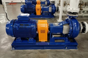
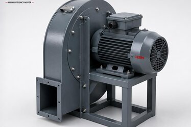
Selecting a centrifugal pump motor is, contrary to common belief, not a matter of copying the kilowatt value on the pump nameplate and ordering a motor of the same power. The correct selection requires reading the relationship between three fundamental variables correctly: flow (Q), head (H) and the power that arises from the combination of the two. This trio is interdependent; change one and the other changes too. Blindly copying the nameplate value usually results in a motor that is either continuously overloaded or oversized.
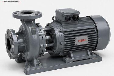
Our focus in this article is general-purpose horizontal and vertical centrifugal pumps. These pumps are used across a wide field, from building water systems to industrial cooling lines, from irrigation to process transfer. Deep-well submersible pumps, fire pumps and booster sets follow a different selection logic and fall outside the scope of this content. For general-purpose centrifugal pumps, correct motor matching is critical for both energy efficiency and the service life of the pump and motor.
Our aim is to enable an engineer or purchasing officer to ask the right questions at the quotation stage. A wrong match, even if invisible on the first invoice, comes back over the operating life as wasted energy, premature failure and unnecessary maintenance cost. Below, we examine the flow-head-power triangle, the concept of the operating point, and the technical criteria to watch in motor selection, step by step.
Flow, Head and Power: Three Interdependent Variables
The key to understanding a centrifugal pump's performance is grasping the relationship between three quantities. These quantities are not independent; when one rises, another typically falls.
- Flow (Q): The amount of liquid the pump delivers per unit time, usually expressed in m³/hour. It defines the flow rate the system requires.
- Head (H): How high or to what pressure the pump delivers the liquid, given in meters of liquid column. It overcomes pipe friction and elevation difference.
- Power (P): Shaped by the product of flow and head, the liquid density and the pump efficiency. It defines the shaft power the motor must provide.
The relationship between these three variables is shown by the pump's characteristic curve. On the curve, as flow increases, head falls. The power the motor draws, however, increases as flow rises. Therefore, wherever the pump is operating, the motor's loading is determined according to that point.
The Operating Point: The Heart of Motor Selection
A centrifugal pump operates not at a single point on its characteristic curve but at an operating point determined by the system's resistance. This point is where the pump curve and the system curve intersect. Motor power must be selected according to this operating point, not according to the pump's nameplate power.
Why Might the Operating Point Have Shifted?
In the field, pumps often operate at a point different from the design point. Throttling a valve, pipe blockage, wrong diameter selection or a change in system resistance over time shifts the operating point. If the operating point shifts to the right of the curve, flow increases and the motor can become overloaded. For this reason, the motor must be selected for the highest power demand at the right-hand end of the curve.
The Non-Overloading Selection Approach
In professional selection, the goal is for the motor not to be overloaded anywhere along the entire pump curve. This is called non-overloading selection. Ensuring the motor does not exceed its rated power even when the valve is fully open provides a safe design for both the motor and the drive. This approach protects the motor against unexpected flow increases.
Factors to Consider When Determining Motor Power
Flow and head alone are not enough for correct power selection. The properties of the liquid and the system conditions must also be taken into account.
- Liquid density: A liquid denser than water (for example a chemical solution) requires more power at the same flow and head.
- Pump efficiency: A low-efficiency pump demands a larger motor to perform the same hydraulic work.
- Viscosity: High-viscosity liquids reduce pump performance and increase power demand.
- Service factor: Defines the motor's capacity to withstand short-term overloads; provides a safety margin.
When these factors are ignored, the motor is either undersized or oversized. An oversized motor means extra payment on the initial investment, low efficiency at light load and a poor power factor. To examine the effect of power factor on operating cost and reactive penalties in more detail, our content on power factor and reactive power in high-efficiency motors will be useful.
Efficiency Class and Operating Cost
Pump motors often run continuously or for long periods. This makes the motor's efficiency class critical in terms of operating cost. IE3 and IE4 class motors provide significant energy savings compared with older standard motors. The annual energy consumption of a pump motor can far exceed its purchase price; for this reason, choosing the efficiency class is the most decisive decision in the long run.
Calculating the total cost of ownership correctly is a far healthier decision-making method than looking only at the sticker price. To address this subject in a quantitative framework, you can make use of our content on total cost of ownership in high-efficiency motors.
Speed Control With a Frequency Inverter
In systems where flow is variable, changing the pump's speed is far more efficient than adjusting flow by throttling a valve. This is where the VFD frequency inverter with an asynchronous motor combination comes into play. When speed is reduced, the power the pump draws falls cubically; this means large energy savings in variable-flow applications.
Maintenance and Long Life
Even a correctly selected motor will not deliver its expected life if left unmaintained. In pump motors, bearing lubrication, vibration monitoring and temperature control must be performed regularly. Our content on the electric motor maintenance and periodic inspection schedule offers a practical guide on how to plan periodic maintenance. Correct product selection and correct maintenance together extend the pump motor's life and minimize unexpected stoppages.
To make the correct match in centrifugal pump motor selection and determine the most suitable motor for your application, you can contact the HEM Motor expert team.
Affinity Laws: The Mathematics of the Pump-Motor Relationship
To truly understand centrifugal pump motor selection, one must know the affinity laws. These laws define the mathematical relationship between the pump's speed and flow, head and power, and explain why correct motor selection is so important.
- Flow is directly proportional to speed: If speed doubles, flow also doubles.
- Head is proportional to the square of speed: If speed doubles, head quadruples.
- Power is proportional to the cube of speed: If speed doubles, power increases eightfold.
This third rule explains why a frequency inverter provides such large energy savings. Reducing the pump's speed only slightly reduces the power drawn by far more. For example, to halve the flow it is enough to halve the speed; in this case power consumption falls to one-eighth. Trying to achieve the same result by throttling a valve wastes energy, because the pump still draws high power.
The affinity laws also guide motor sizing. In a variable-flow system, the motor must be selected for the power demand at maximum speed and maximum flow; however, since the system will most often operate below this point, large savings are achieved with a frequency inverter.
Motor Matching Differences in Horizontal and Vertical Centrifugal Pumps
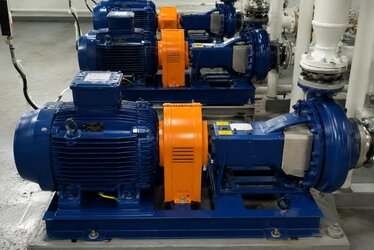
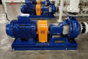
General-purpose centrifugal pumps are produced with horizontal and vertical frame designs, and different details stand out in the motor matching of each. In horizontal pumps, the motor is usually connected to the pump shaft through a coupling; in this case, axial alignment and vibration control become critical. In vertical pumps, the motor is often mounted directly on top of the pump, and axial load-carrying capacity comes to the fore.
- Horizontal centrifugal pump: The coupling connection requires correct alignment; misalignment leads to bearing and vibration problems.
- Vertical centrifugal pump: The motor's axial load-carrying capacity and special bearing design gain importance.
- Close-coupled pump: The motor shaft directly carries the impeller; compact but motor selection is more sensitive.
Correct motor selection must take these design features of the pump into account. Otherwise, even a motor selected at the correct power cannot deliver its expected life due to mechanical mismatch.
NPSH and Cavitation: Factors That Indirectly Affect Motor Load
A frequently overlooked subject in centrifugal pump selection is NPSH (Net Positive Suction Head) and the associated risk of cavitation. When there is insufficient pressure on the suction side, vapor bubbles form inside the pump; these bubbles collapse on the impeller, causing both mechanical damage and irregular load. Irregular load in turn causes the motor to run with vibration and inefficiency.
The indirect effects of cavitation on the motor can be summarized as follows:
- Irregular load increases the motor's vibration and shortens bearing life.
- When pump efficiency falls, the motor draws more power to do the same work.
- Continuous cavitation disturbs pump balance through impeller damage and strains the motor.
For this reason, when selecting a motor, not only flow and head but also suction conditions must be evaluated. A healthy suction design ensures the motor too runs smoothly and with a long life.
A Step-by-Step Checklist for Correct Selection
A logical sequence to follow when selecting a centrifugal pump motor minimizes the probability of error. The steps below can be used as a checklist at the quotation stage.
- Step 1: The real flow (Q) and head (H) the system requires are determined.
- Step 2: The operating point is found on the pump's characteristic curve.
- Step 3: Non-overloading power is selected by considering the highest power demand at the right-hand end of the curve.
- Step 4: Power is corrected by accounting for liquid density, viscosity and pump efficiency.
- Step 5: Efficiency class (IE3/IE4), mounting configuration and protection class are determined according to the application.
- Step 6: If flow is variable, the need for a frequency inverter is assessed.
This systematic approach prevents both overloading and oversizing mistakes. Selecting the right motor on the first attempt is the smartest path in terms of both time and cost.
Frequently Asked Questions
Can I use the kW value on the pump nameplate directly for motor selection?
No. The nameplate value is only a starting point. What truly matters is the power the pump requires at its actual operating point. If the operating point has shifted from the design point, a motor selected by nameplate power can become overloaded. For this reason, the flow-head curve and system conditions must be evaluated together.
What is the drawback of selecting an oversized motor?
An oversized motor means extra payment on the initial investment. In addition, when the motor runs at light load, its efficiency falls and its power factor worsens, which can lead to reactive power penalties. Correct sizing provides the most economical solution in terms of both energy and investment.
Is a frequency inverter necessary in a variable-flow system?
In applications where flow changes frequently, a frequency inverter offers a major advantage. Adjusting flow by reducing pump speed is far more efficient than throttling a valve, because power consumption decreases cubically in proportion to speed. In constant-flow systems, however, a correctly sized direct-on-line start may be sufficient.