English
 Türkçe
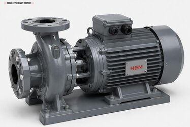
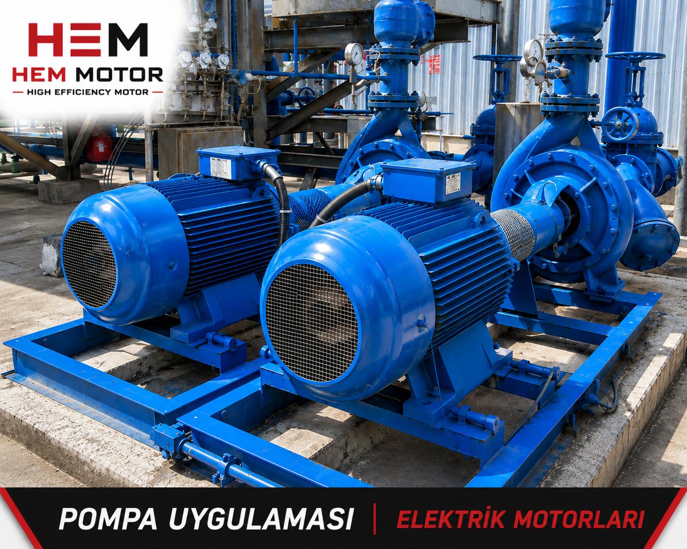
When selecting electric motors for pump, fan and exhaust (aspirator) applications, engineers usually focus on power (kW), speed and efficiency class (IE3/IE4). Yet one critical quantity that directly affects the plant's electricity bill and grid compatibility is often overlooked: the power factor (cos φ). Induction motors draw reactive power from the grid to build their magnetic field. This reactive power performs no useful work; it neither turns into heat nor mechanical motion, it is simply energy that flows back and forth to magnetize the machine. As a result, the apparent power (kVA) drawn at the motor terminals is larger than the actual work done (kW). The ratio between the two is the power factor, and in pump/fan motors a poor power factor — when left uncompensated — leads to reactive energy penalties from the utility and unnecessary loading of cables, fuses and transformers.
In this article, HEM Motor explains in practical terms why power factor drops in pump and fan motors, how cos φ deteriorates especially at low load, how terminal (unit) compensation with a capacitor connected in parallel to the motor terminals works, the logic of capacitor sizing, and why connecting a capacitor to a VFD-driven motor is dangerous. Our goal is to help you select the right motor together with the right compensation approach.
What Is Power Factor (cos φ) and Why Does It Matter in Pump/Fan Motors?
In an induction motor the total current splits into two components: active current (which turns the load and produces kW) and reactive current (which builds the magnetic field and produces kVAr). The power factor is the ratio of active power to apparent power: cos φ = kW / kVA. The closer this value is to 1, the more efficiently the motor uses the grid. A typical IE3 four-pole pump motor has a cos φ of around 0.82–0.86 at full load. However, when the pump or fan does not run at full load, this value drops rapidly.
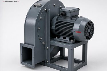
The importance of reactive power comes from the fact that distribution utilities apply a reactive energy charge (penalty) when the ratio of reactive to active energy exceeds a defined limit. In continuously running but frequently part-loaded applications — pumping stations, circulation lines, cooling-tower fans and ventilation aspirators — a low power factor turns into a visible cost item at the end of the month.
Why Does the Power Factor Drop Even More at Low Load?
The motor's magnetizing current is almost independent of load; the motor draws roughly the same reactive current to build its magnetic field whether it runs idle or at full load. The active current, by contrast, rises and falls with load. If a pump throttles against a partly closed valve, or a fan damper is choked, the motor runs at low load; the active component shrinks while the reactive component stays the same, so cos φ falls significantly. Values dropping to around 0.70 at half load and 0.55 at quarter load are common in the field. For this reason, oversized pump/fan motors (chosen far larger than the load requires) are disadvantaged in both efficiency and power factor. Correct power selection is the first step, even before compensation.
Terminal (Unit) Compensation: A Capacitor in Parallel with the Motor
There are two common ways to correct reactive power: central compensation (an automatic capacitor bank in the main panel) and unit/terminal compensation (a capacitor connected directly in parallel to the motor terminals). For standalone loads that run continuously at fixed speed, such as pumps and fans, terminal compensation is very practical: the capacitor switches in and out together with the motor, needs no separate contactor or reactive relay, and because it supplies the reactive current right at the source (the motor terminals) it also relieves the supply cable.
In terminal compensation the capacitor is connected in parallel (usually in delta) to the three phases of the motor, on the motor side of the motor contactor. Thus the capacitor is energized when the motor is energized and disconnected when the motor stops. This means the motor and capacitor are switched together, which simplifies the control scheme.
The Logic of Capacitor Sizing
The most critical rule in terminal compensation is this: the capacitor power (kVAr) must NOT exceed the motor's no-load (unloaded) magnetizing reactive power. Otherwise a risk of self-excitation arises: when the motor is disconnected from the grid, the capacitor and motor windings form a resonant circuit, and the voltage generated by the coasting motor can rise to dangerous levels. This harms the insulation and damages equipment on re-energization (especially during water hammer or reverse rotation in pumps). The practical rule, therefore, is to size the capacitor to supply about 90% of the motor's no-load reactive current. The table below summarizes the capacitor-sizing logic commonly used for four-pole standard induction motors (the exact value should be based on the no-load current on the nameplate and the manufacturer's data).
| Motor Power Range | Typical Full-Load cos φ | Suggested Terminal Capacitor (approx. kVAr) | Note |
|---|---|---|---|
| 0.75 – 1.5 kW | 0.78 – 0.80 | 0.5 kVAr | Small circulation pumps |
| 2.2 – 4 kW | 0.80 – 0.82 | 1 – 1.5 kVAr | Fans and medium pumps |
| 5.5 – 7.5 kW | 0.82 – 0.84 | 2 – 2.5 kVAr | Exhaust, pressurization |
| 11 – 18.5 kW | 0.84 – 0.86 | 4 – 6 kVAr | Large fan/pump |
| 22 – 37 kW | 0.85 – 0.87 | 7.5 – 12 kVAr | Verify no-load current |
The table values are a starting reference, not a binding calculation. For correct sizing, use the no-load current (I0) on the nameplate or the manufacturer's no-load reactive power, and keep the capacitor below that value.
Compensation Warning for VFD-Driven Pump/Fan Motors
In modern pump and fan plants, VFDs (variable frequency drives) are widely used for variable speed. Here a very important rule applies: never connect a compensation capacitor to the VFD output, i.e. between the drive and the motor. The drive output is not a sine wave but a high-frequency pulsed (PWM) voltage. A capacitor connected in parallel to this output draws very high pulse currents, heats up and bursts within a short time, or damages the drive's output stage. Moreover, such a capacitor cannot perform reactive compensation anyway.
The good news is this: thanks to the drive's rectifier front end, the power factor on the grid (input) side of a VFD-driven motor is already quite high (typically 0.95 and above). So in a VFD system, classic motor compensation is usually unnecessary. In a drive system the real issue is not reactive power but harmonics (THD); if needed, a line choke (line reactor) or harmonic filter is applied on the input side. If compensation capacitors are required, they must be used only on the grid-input side of the drive and be of a harmonic-resistant (detuned/reactor) type; a directly paralleled fixed capacitor risks harmonic resonance.
Practical Checklist for Correct Selection
- Is the motor directly connected to the grid, or driven by a VFD? If there is a VFD, no capacitor is connected to the motor terminals.
- Does the pump/fan run continuously at fixed speed? If yes, terminal compensation is a practical solution.
- Does the capacitor value exceed the motor's no-load reactive power? It must not (self-excitation risk).
- Is the motor oversized relative to the load? Select the correct power first; low load hurts both efficiency and cos φ.
- If the plant has many motors, a central automatic compensation panel may be more flexible.
- Are the capacitor and motor switched together? Switching in and out together is important for safety.
Motor and Compensation Approach by Pump and Fan Application
For a fixed-flow pressurization pump or a continuously running exhaust aspirator, a correctly sized IE3/IE4 motor plus terminal compensation is sufficient and economical in most cases. By contrast, in a process pump whose flow or pressure constantly varies, or an air-handling-unit fan whose damper constantly modulates, a VFD-based solution provides both energy savings and smooth operation; in this case no capacitor is connected to the motor terminals, and harmonic measures are taken on the input side if needed. Choosing an efficient motor also reduces the burden on compensation: IE4 class motors generally offer better power factor values.
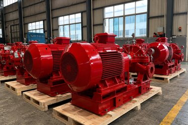
As HEM Motor, we supply a wide range of powers and speeds in IE3 and IE4 efficiency classes from stock for pump, fan and exhaust applications; we evaluate the right motor and the right compensation approach for your application together.
How Reactive Penalties Arise and How Compensation Lowers the Bill
Distribution utilities assess the reactive energy a plant draws relative to its active energy. When the ratio of inductive reactive energy to active energy exceeds a defined threshold, a separate charge is billed for the reactive energy consumed. In a pump- and fan-heavy plant where most motors run at part load, this ratio is easily exceeded. Compensation produces a large part of the reactive power the motors need inside the plant, via capacitors, thereby reducing the reactive energy drawn from the grid. The result is that the penalty disappears and more active power can be carried over the same cable and transformer, because the apparent power (kVA) drops.
The practical benefit is not only the bill. When the power factor is corrected, the total current flowing through the supply cable and transformer decreases. This lowers cable losses (I²R), reduces heating of the transformer and panel, and frees up more headroom in the existing infrastructure for future capacity increases. Especially in plants with long supply lines, such as pumping stations, terminal compensation also improves the voltage drop along the line somewhat, because the reactive current is supplied at the source and not carried along the line.
Central Compensation or Terminal Compensation?
Both methods have their place, and the right choice depends on the plant structure. Terminal (unit) compensation is ideal for large pump/fan motors that run standalone, continuously and at fixed speed. Because the capacitor switches in and out with the motor, control is simple, no separate reactive power relay is needed, and the reactive current is supplied right next to the motor. Its drawback is that when the motor stops, the capacitor is also disconnected; so it is not suited to finely tuning total compensation in a variable plant profile.
Central compensation, by contrast, is done in the main panel with stepped capacitor banks and a reactive power relay. The relay measures the plant's instantaneous reactive load and switches the steps in and out to keep the power factor on target. In plants combining many small motors, lighting and variable loads, central compensation is more flexible. In practice, many plants use both together: terminal compensation for large, continuously running pump/fan motors, and a central automatic panel for the rest of the variable load. The key is that the sum of the capacitors must not push the plant to the capacitive side; over-compensation causes a separate penalty as well.
Common Mistakes in Compensation
- Connecting a capacitor to the VFD output: destroys both the capacitor and the drive.
- Sizing the capacitor larger than the motor's no-load reactive power: risk of self-excitation and overvoltage.
- Leaving the capacitor permanently energized, independent of the motor: causes a capacitive shift and over-compensation at night when the motor stops.
- Choosing an oversized motor and trying to fix it with compensation: the root cause is low-load efficiency; the correct power must be selected first.
- Using a non-detuned (no reactor) capacitor in a plant with high harmonic content: harmonic resonance and capacitor failure.
- Skipping periodic maintenance of capacitors: a drying/weakening capacitor loses capacitance and compensation silently degrades.
The Relationship Between Motor Efficiency Class and Power Factor
Efficiency class (IE3, IE4) and power factor are different quantities; one describes losses, the other the reactive power demand. In practice, however, high-efficiency motors usually have a better-designed magnetic circuit and lower losses, so they often offer somewhat better power factor values than a lower-class motor of the same rating. This eases the compensation burden. In applications that run thousands of hours per year — pumps, fans and aspirators — choosing IE4 instead of IE3 reduces both energy consumption and reactive load, lowering total cost of ownership. Correct motor selection is the step that precedes and simplifies the compensation decision.
In short, the order is clear: first select a motor suited to the application, not oversized and, where possible, of a high efficiency class; then, if the motor is connected directly to the grid, apply terminal compensation of the correct value; if the motor is driven by a VFD, do not connect a capacitor on the motor side, and take harmonic measures on the grid input side if needed. These three steps improve the electrical performance of your pump and fan plant holistically.
Frequently Asked Questions
Can I connect a capacitor directly to my pump motor terminals?
Yes; if the motor is connected directly to the grid (no VFD) and the capacitor value does not exceed the motor's no-load reactive power, connecting the capacitor in parallel to the motor terminals (terminal/unit compensation) is a safe and practical method. The key is that the capacitor is switched together with the motor and not oversized.
Does my VFD-driven fan motor need a compensation capacitor?
No, not on the motor side, and it must not be connected there. Connecting a capacitor to the drive output destroys both the capacitor and the drive. The power factor at the VFD grid input is already high; if the problem is harmonics, a line reactor or filter is applied on the input side.
What happens if I oversize the capacitor?
An oversized capacitor can both cause a capacitive (leading) reactive penalty and, when the motor is disconnected from the grid, generate dangerous overvoltage through self-excitation. This stresses the insulation and damages equipment on restart. The capacitor must always be sized below the motor's no-load reactive power.
The right motor power, the right compensation and, where needed, the right drive selection directly improve both your plant's energy cost and its grid compatibility. To get a quote with fast delivery from the HEM Motor stock range for your pump, fan and exhaust motor needs, get in touch with us.
Related content: grounding and EMC in VFD systems, reading cos φ and efficiency on the IE3 nameplate, the IE4 threshold in pumps, fans and compressors and running below 50 Hz and torque.