English
 Türkçe
Anyone who manages a maintenance store or a spare-motor stock knows it: dozens of motors held separately at the same power and speed, differing only in mounting type, take up space and tie up capital. This is exactly where IE3 efficiency-class multi-mount (universal frame) motors come in. Because a B35-frame motor can be connected both by its feet (like a B3) and by its front flange (like a B5), a single stock code covers more than one need. In this article we cover the B3, B5 and B35 mounting codes in an IE3 motor, the flange dimensions (FF and FT types), how the universal frame ensures compatibility in replacement, the stock-reduction advantage and the details of correct selection. At HEM Motor our goal is to supply the IE3 motor in the right mounting type from stock with fast delivery, reducing your stock burden and providing installation flexibility in the field.
Mounting Codes: What Are B3, B5 and B35?
The IEC 60034-7 standard defines motor mounting arrangements with IM (International Mounting) codes. The three most used in practice are B3, B5 and B35. These codes determine how the motor connects to the machine and which surface carries it.
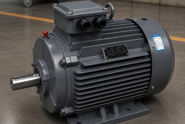
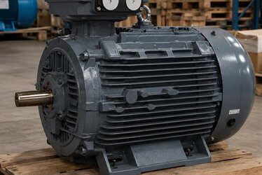
- B3 (IM B3 / IM 1001): Foot mounting. The motor is fixed to the floor or a base by the feet under its frame. Drive is usually by coupling or belt-pulley. It is the most common general-purpose mounting.
- B5 (IM B5 / IM 3001): Flange mounting. The motor's front end shield has a large-diameter drilled flange; the motor is bolted directly to the machine or gearbox by this flange. There are no feet.
- B35 (IM B35 / IM 2001): Combined mounting. The motor has both feet and a front flange; that is, it can act as both B3 and B5 at once. It is the most flexible option.
Reading the mounting code correctly is critical for an error-free order; our IM mounting code reading guide explains the B3, B5 and V1 codes in detail.
Why Is the Universal Frame (B35) Advantageous?
The B35 motor we call the universal frame combines two mounting options in one product. The practical benefit is large. If in a plant some machines at the same power want a foot (B3) motor and others a flange (B5) motor, you would normally need spares of both. But because the B35 motor satisfies both cases, holding a spare as a single item is enough. This both reduces the number of stock items and removes the risk of ordering a motor in the wrong mounting type.
| Mounting | Feet | Flange | Typical use | Replacement flexibility |
|---|---|---|---|---|
| B3 | Yes | No | Coupling/belt drive, floor mounting | Only in place of foot |
| B5 | No | Yes (FF) | Gearbox, pump, direct flange connection | Only in place of flange |
| B35 | Yes | Yes (FF) | Both foot and flange need | In place of both B3 and B5 |
As shown, B35 offers the widest flexibility in replacement. A B35 motor can be fitted in place of both a B3 motor and a B5 motor; this makes it the most valuable item in a spare stock.
Flange Dimensions: FF and FT Types
In flange motors the flange type and size are critical for the motor to fit the machine exactly. There are two basic flange types: FF (clearance-hole / drilled flange) and FT (tapped / face flange). B5 and B35 motors usually use a large FF-type flange, while at smaller powers a B14 mount has an FT-type face flange. Flange dimensions are defined with standard codes; for example FF265, FF300, FF350. The number here shows the pitch circle diameter of the bolt holes on the flange (not the pilot diameter).
| Frame (approx.) | Typical flange code | Bolt circle diameter | Pilot (spigot) diameter |
|---|---|---|---|
| 90 | FF165 | 165 mm | 130 mm |
| 100-112 | FF215 | 215 mm | 180 mm |
| 132 | FF265 | 265 mm | 230 mm |
| 160 | FF300 | 300 mm | 250 mm |
| 180-200 | FF350 | 350 mm | 300 mm |
| 225-250 | FF500 | 500 mm | 450 mm |
When replacing, not only power and speed but also the flange code and pilot diameter must match the old one; otherwise the motor will not seat on the machine. The values are typical and small differences may occur by series, so sharing the existing motor's nameplate and flange code is the safest approach.
IE3 Efficiency Class and Regulation
While seeking the multi-mount advantage, the efficiency class must not be overlooked. The IE3 (Premium efficiency) class is the basic requirement of the current efficiency regulation for three-phase induction motors and is mandatory over a wide power range. When universal-frame B35 motors are also produced in the IE3 class, both mounting flexibility and regulatory compliance are provided together. This should be the standard expectation in both new purchases and replacements.
- IE3 is the basic efficiency class mandated by regulation at most powers.
- In long-running applications, moving up to IE4 can lower life-cycle cost.
- The efficiency class is clearly written on the motor nameplate; always check it in replacement.
You can examine the efficiency requirement in our efficiency class mandate and IE3 and IE4 regulation articles, and the frame-shaft table in our shaft diameter and frame table article.

Replacement Compatibility: What to Watch For
When replacing an existing motor with a universal-frame IE3 motor, several dimensions must be matched to guarantee mechanical compatibility. It is not enough that only the kW and speed are the same; for the motor to physically seat on the machine the following points must be checked.
- Shaft diameter and length: The coupling or pulley must fit the shaft exactly; a shaft diameter difference requires a coupling change.
- Shaft height (frame size): In foot mounting the height of the shaft axis from the floor must match the machine's drive axis.
- Foot hole spacing: In B3 and B35 the foot bolt-hole spacing must fit the base.
- Flange code and pilot diameter: In B5 and B35 the flange must seat exactly on the mating surface of the machine.
- Terminal box orientation: Having the cable entry on the right side eases installation.
All these dimensions can be confirmed with the type code and frame information on the motor nameplate. In replacement orders, sharing a photo and the nameplate of the old motor reduces the risk of the wrong product to almost zero. To decode the frame, pole, mounting and option letters, our order code decoding guide helps.
Stock Reduction and Cost Advantage
The most concrete benefit of universal-frame motors is reducing the number of spare stock items. Suppose a plant uses a 7.5 kW 4-pole motor in both foot and flange versions. In the classic approach you must hold spares of both; that means two separate stock items, two separate capital commitments and two separate shelf spaces. With a B35 universal frame, a single spare motor covers both needs. This reduces tied-up capital, simplifies warehouse management and removes the risk of having the wrong mounting type in an emergency failure.
- One stock item instead of two mounting types: less tied-up capital.
- The risk of ordering the wrong mounting type disappears.
- In an emergency failure, your single spare fits both needs.
- Warehouse and shelf management is simplified.
This advantage is especially pronounced in plants with many machines where downtime is costly. You can find the most sought-after power and speed combinations in our IE3 stock guide article.
Which Mounting for Which Application? A Practical Guide
Choosing the right mounting type depends on the application's mechanical layout. Foot (B3) mounting is ideal where the motor sits on a base and connects to the machine by coupling or belt-pulley; conveyor drives, ventilators, compressors and most general machine applications are in this group. Flange (B5) mounting is preferred in compact layouts where the motor is bolted directly to a gearbox, pump body or the front face of the machine; it is common in close-coupled pumps, flange-mounted gearboxes and where floor space must be saved. B35, covering both cases, is the most sensible choice when it is not yet clear which way the design will go or when the same motor will circulate among different machines.
Another practical criterion is the loads from the drive. Belt-pulley drive imposes a radial load on the shaft end; in that case foot (B3) mounting is usually more suitable because the load is transferred to the base through the feet. In directly coupled, axially aligned connections, flange mounting can be advantageous in terms of compactness and vibration. In motors mounted directly to a gearbox, the flange provides both the mechanical connection and the centering (thanks to the pilot diameter) in one step, reducing alignment error.
- Coupling/belt drive, floor mounting: usually B3 (foot).
- Direct connection to gearbox/pump, compact layout: usually B5 (flange).
- Cases needing flexibility, many machines or undecided design: B35 (combined).
- Precise mounts needing a small-power face flange: B14 (FT flange).
Mounting Position and Terminal Box Orientation
An often-missed detail in multi-mount selection is the motor's operating position and the terminal box orientation. The B3, B5 and B35 codes are for a horizontal shaft axis; if the motor will run vertically (shaft up or down), V-coded mountings (such as V1, V5) come into play and additional considerations like the oil seal, bearing lubrication and drainage arise in these positions. Therefore, in replacement, not only the B code but the motor's real operating position must be evaluated.
The terminal box orientation also directly affects installation ease. Although on most motors the terminal box is on top, in some applications the cable entry may need to come from the side; on many motors the terminal box can be rotated in 90-degree steps. In tight panels and special cable routes this detail directly affects installation time and cable order, so it is useful to clarify it at the order stage. For vertical mounting and shaft-down position our vertical mounting V1/V5 article, and for the right choice in geared use our monoblock geared motor guide will help.
Pre-Order Checklist and Common Mistakes
The most common mistake in ordering a universal-frame IE3 motor is looking only at power and speed and skipping the mounting details. Yet whether the motor seats on the machine depends on the agreement of millimetric dimensions. Applying the following checklist before ordering largely prevents errors. First, clarify the application's power and speed need. Then determine the mounting type (B3, B5, B35) and, if needed, the flange code (for example FF265). Compare the shaft diameter, shaft height and foot hole spacing with the existing motor. Confirm the efficiency class is IE3 (or IE4 as required). Check the terminal box orientation and cable entry side. Finally, evaluate the operating position (horizontal/vertical) and environmental conditions. A frequent error is confusing the B5 with the B14 flange; B5 is the large FF flange while B14 is the small FT face flange, and the two are not interchangeable. Another is ignoring the pilot (spigot) diameter; even if the bolt circle is right, the motor will not center if the pilot diameter does not match.
Frequently Asked Questions
Can I really fit a B35 motor in place of both foot and flange?
Yes. A B35 motor has both feet and a front flange; so it can be connected by its feet in a B3 (foot) application and by its flange in a B5 (flange) application. The only condition is that the flange code and shaft dimensions suit the machine. This way a single B35 motor covers two different mounting needs and provides great flexibility in spare stock.
What is the difference between FF and FT flanges?
FF is a clearance (drilled) flange; it has holes through which the bolts pass and is usually the large flange of B5/B35 motors. FT is a tapped face flange, used mostly in smaller-power B14 mounting. In replacement, matching the existing motor's flange type and code (for example FF265) is essential for the motor to seat properly on the machine.
In replacement, is it enough that only kW and speed match?
No. Even if kW and speed are the same, for the motor to physically seat on the machine the shaft diameter, shaft height, foot hole spacing and flange code/pilot diameter must also be compatible. The safest way is to share the type code and mounting information on the old motor's nameplate; then we guarantee the correct replacement.
Get the IE3 Motor in the Right Mounting Type from HEM Motor
For your multi-mount IE3 motor needs, let us determine the right mounting type, frame size and flange dimension together. With HEM Motor's broad manufacturer stock and fast delivery, we supply the IE3 motor in B3, B5 and B35 mounting options quickly. With the universal-frame choice, reduce your stock burden and gain mounting flexibility. Share your application and current motor nameplate; contact us to request a quote for the most suitable motor.