English
 Türkçe
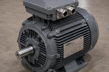
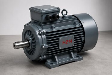
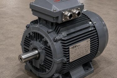
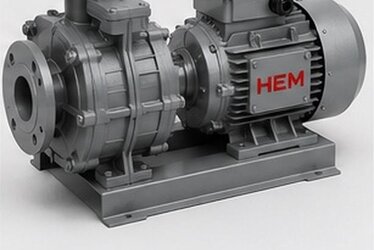
When you design a conveyor, mixer, filling line, crane traverse drive or a packaging machine, you almost always face the same need: converting a high-speed motor into a low-speed, high-torque output. There are two ways to do this; buying the motor and gearbox separately and joining them with a coupling, or choosing a monoblock gearmotor in which they are combined in a single body. In an era when efficiency regulations mandate IE3 motors, the right choice determines both energy cost and ease of installation. In this article we address the B5/B14 connection difference, how output speed is determined, and what you need to know for the right supply when selecting a monoblock gearmotor built with an IE3 efficient motor.
At HEM Motor we offer both separate motor + gearbox and compatible monoblock solutions. To recommend the right combination, the application's output speed, torque need and installation conditions are decisive. For power-ratio combinations and current electric motor prices, you can look at our product pages.
Monoblock Gearmotor or Separate Motor + Gearbox?
Both approaches have their place. A monoblock gearmotor is a compact solution in which the motor and gearbox are combined compatibly by a single manufacturer. A separate motor + gearbox is formed by mounting an IEC-frame motor onto a flanged gearbox.
- Monoblock advantage: More compact, fewer connection points, a factory-matched shaft-flange transition, and less alignment hassle during installation.
- Separate combination advantage: When the motor fails, it is possible to replace only the motor; stock and service flexibility are higher; thanks to the IEC standard, there is a wide motor choice.
We compared the two approaches from a purchasing and maintenance standpoint in our article geared motor or separate motor + gearbox? We explain the monoblock selection process step by step in our article on monoblock geared motor purchasing.
B5 or B14? The Key to the Gearbox Connection
When selecting a monoblock gearmotor or a separate motor to mount on a gearbox, the most critical mechanical decision is the motor's front flange type. There are two common flange connections in the IEC standard:
B5 Large Flange
B5 connects via the large flange on the motor's front cover, with peripheral bolt holes. It is preferred on larger-frame motors and high-torque gearbox connections. The large flange transmits torque more securely.
B14 Small Flange
B14 is a smaller, more compact flange connected directly via threaded holes on the front flange. It is common in small and medium-power gearbox applications, especially on compact aluminum-body motors. The hole dimensions and pilot diameter of the B14 must match the gearbox's input flange exactly.
- Can B14 be fitted instead of B5? No, not directly; the flange diameter, hole pattern and pilot diameter differ. Whichever type the gearbox's input flange requires, the motor must be of that type.
- Pilot diameter and hole pattern: Even at the same frame size, B5 and B14 dimensions differ; the gearbox connection dimensions must be clear before ordering.
Our articles B5 flange or B14 flange? and B14 small flange and gearbox connection in IE3 motors are reference sources for correct flange matching.
Output Speed and Reduction Ratio
The heart of gearmotor selection is the output speed (rpm) and output torque your machine requires. The ratio between the motor speed and your desired output speed determines the gearbox reduction ratio.
- Output speed: A standard 4-pole motor runs at roughly 1400-1500 rpm. With a 1/30 ratio gearbox, the output becomes roughly 46-50 rpm. Clarifying the output speed you need is the first step in selection.
- Output torque: As speed decreases, torque increases. The gearbox must be sized to produce the torque your machine requires at the output.
- Gearbox type: A worm gearbox provides a 90-degree output and high ratio; a bevel-helical gearbox is suitable for higher efficiency and high power.
We collected gearbox selection by ratio, torque and output speed in our article reducer selection guide. To match the right motor to a gearbox, our article which electric motor fits a worm and NMRV gearbox? explains IEC frame and flange matching.
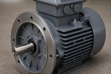
Why an IE3 Efficient Motor?
A gearmotor is generally used in applications that run long hours per day, such as conveyors and mixers. Efficiency regulations mandate IE3 in a certain power band; furthermore, in a continuously running drive, the low losses of an IE3 motor are directly reflected in the annual energy bill. In both the monoblock solution and the separate combination, choosing an IE3 efficient motor on the motor side is the right decision for both regulatory compliance and operating cost. You can review the suitable motor range for gearboxes on the electric motors for gearboxes page, and gearbox options on the worm gear reducers page.
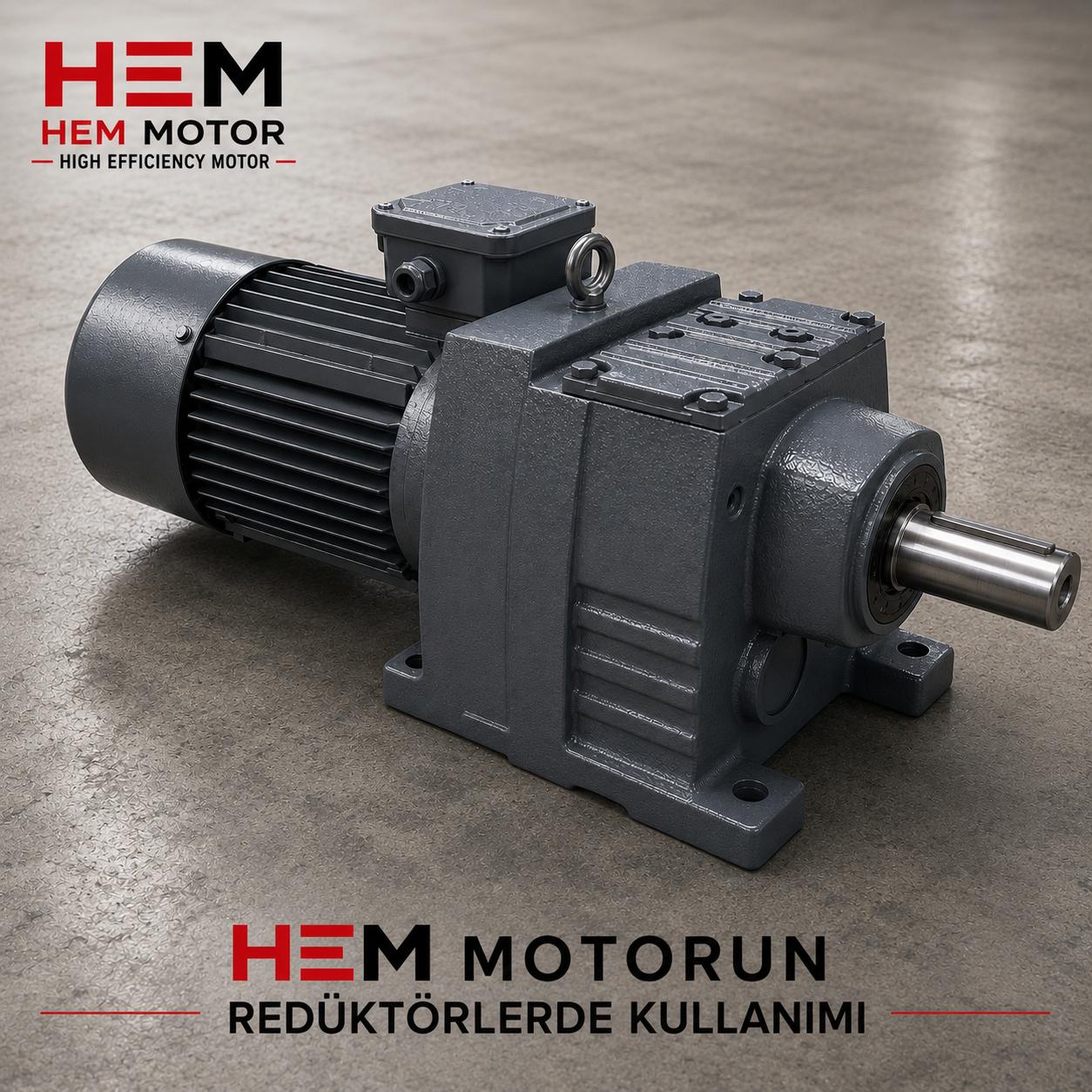
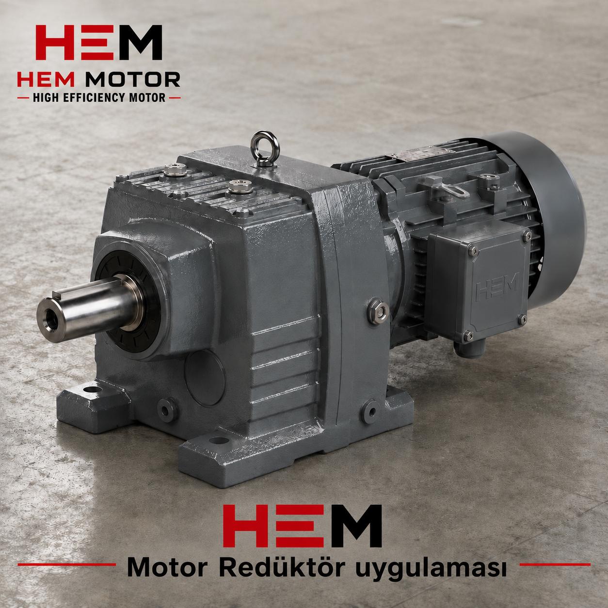
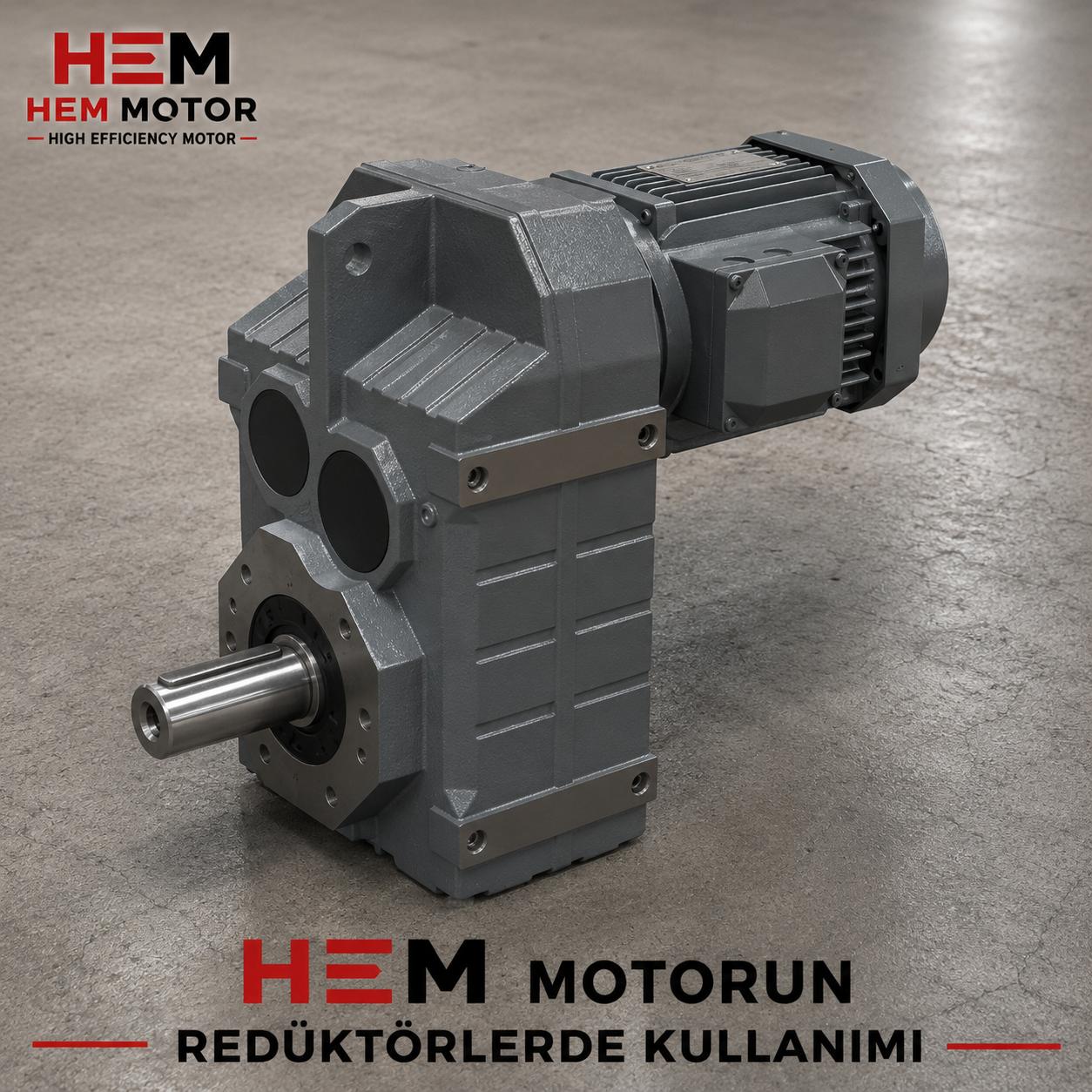
Gearmotor Selection by Gearbox Type
In monoblock gearmotor selection, the gearbox type is determined according to the application's needs as much as the motor side. HEM-series worm gearboxes and K-series bevel-helical gearboxes answer different needs.
Worm Gearmotor
A worm gearbox provides an output at 90 degrees to the motor axis and reaches a high reduction ratio in a single stage. Due to its compact structure and quiet operation, it is common on conveyors, mixers and filling lines. At certain ratios, the self-locking feature prevents the load from running back; this feature is especially valuable in lifting and inclined-conveyor applications. We explain the self-locking logic in our article on self-locking in worm gearboxes.
Bevel-Helical Gearmotor
A bevel-helical gearbox provides higher efficiency and greater power transmission than a worm gearbox. It also gives a 90-degree output but runs more economically in long-duration, high-power applications. We compared which is more advantageous in which application in our article in which jobs is a K-series bevel-helical gearbox more economical than a worm gearbox?
Mounting Position and Output Shaft
There are two often-overlooked topics in gearmotor selection that directly affect installation: the gearbox mounting position and the output shaft type. A gearbox ordered in the wrong position can create installation problems and lubrication faults in the field.
- Mounting position: A gearbox can be mounted horizontally, vertically or at different angles. Since the mounting position affects oil level and lubrication, it must be specified in the order.
- Output shaft type: There are options such as solid shaft, hollow (bore) shaft or flanged output. Your machine's connection type determines the output shaft type.
- Drive direction: Some applications require bidirectional operation; this is also an input to the gearbox selection.
We address mounting positions and lubrication in detail in our article on gearbox mounting positions (M1–M6) and lubrication.
Details of IEC Frame and Flange Matching
In a separate motor + gearbox combination, the key to building a properly functioning drive is that the motor's IEC frame size and flange dimensions match the gearbox input side exactly. The IEC standard defines a certain relationship between frame size and flange dimensions; however, since each frame may have both B5 and B14 options, the dimensions must be confirmed carefully.
- Frame size: The motor's IEC frame size (for example 63, 71, 80, 90, 100) determines the shaft diameter and flange dimensions. The gearbox's input flange is designed to accept certain frame sizes.
- Pilot diameter (spigot): The flange's centering spigot axially aligns the motor with the gearbox. If the pilot diameter does not match exactly, the motor will not seat properly.
- Hole pattern (PCD): The diameter and distribution of the bolt holes on the flange must be the same as the gearbox's connection face.
- Shaft diameter and key: The motor's shaft must be of a diameter and key size suitable for the gearbox's input bore.
HEM-series worm gearbox bodies accept certain IEC motor connections; for example, small bodies match IEC 56/63 and medium bodies IEC 71/80/90 motors. You can find the details of this matching in our article which electric motor fits a worm and NMRV gearbox? and the frame-shaft table in our article on shaft diameter and frame table in IE3 motors (IEC 56-355).
Output Speed Calculation and Correct Ratio Selection
The most concrete step in gearmotor selection is finding the reduction ratio by working backward from the output speed your machine needs. This calculation is simple but must be done correctly.
First you determine the output speed your machine requires. Then you obtain the required reduction ratio by dividing the speed of the motor you will use (a 4-pole motor at roughly 1400-1500 rpm, a 2-pole at roughly 2800-3000 rpm) by this output speed. For example, for a motor speed of roughly 1400 rpm and a desired output of roughly 47 rpm, the ratio is around 1/30.
- Torque rises as speed falls: As the reduction ratio increases, the output speed drops and the output torque rises. For this reason, applications requiring high torque need a high-ratio gearbox.
- Rounding to standard ratios: Gearboxes are produced in standard ratios (for example 1/10, 1/20, 1/30, 1/50). The standard ratio closest to your need is selected; if necessary, fine-tuning is done with a pulley-belt.
- Motor speed selection: The same output speed can be reached with different motor speed and ratio combinations; the most suitable combination is evaluated in terms of efficiency and cost.
We explain output speed and ratio selection in small single-phase 220V powers in detail in our article on 220V single-phase geared motor selection: output speed, reduction ratio and small-power stock guide.
Service Factor and Load Profile
One of the most important factors determining the life of a gearmotor is the gearbox's service factor. The service factor shows how much safety margin the gearbox is selected with relative to real operating conditions. A continuous and impact load requires a higher service factor than a short-duration, smooth load.
- Operating time: How many hours per day it runs (for example, single shift or three shifts) affects the service factor.
- Load type: The classification of smooth, light-impact or heavy-impact load determines the required safety margin.
- Start frequency: Frequent start-stops create additional load on the gearbox and motor and raise the service factor.
We collected the factors affecting price and selection in geared motors in our article on factors affecting the price of a geared motor.
Frequently Asked Questions
Should I buy a monoblock gearmotor or a separate motor + gearbox?
If you want compactness, fewer connection points and a factory-matched transition, a monoblock gearmotor is advantageous. If replacing only the motor in a failure, a wide motor choice and service flexibility are your priority, an IEC-frame separate motor + gearbox combination makes more sense. The decision depends on your maintenance strategy and stock approach.
Should I fit a B5 or B14 motor to the gearbox?
This depends on the type the gearbox's input flange requires. The B5 large flange is used in larger frames and high-torque connections; the B14 small flange in small-to-medium-power compact applications. The two flanges are not directly interchangeable; before ordering, the gearbox's flange type, pilot diameter and hole dimensions must be clarified.
How do I obtain the output speed I want?
You find the required reduction ratio by dividing the motor speed (for example, roughly 1400-1500 rpm at 4 poles) by your desired output speed. Since torque increases as speed decreases, the gearbox is sized considering both the output speed and the output torque together. When you send us your need (output rpm and torque), we recommend the suitable motor-gearbox combination.