English
 Türkçe
When you build a geared drive system, the most critical yet most overlooked detail is how the motor connects to the gearbox. Most plants get the power and reduction ratio right, but treat the B14 flange dimension, the spigot register diameter and the shaft fit as afterthoughts. Yet if the mechanical interface between motor and reducer is wrong, the system will vibrate, overheat, leak oil past the seal and chew through bearings — no matter how good the motor inside it is. In this guide we explain, from the IE3 motor side, what the small flange (B14) connection actually is, how its dimensions work, why centering matters, and how to match a motor to a reducer correctly — from both an engineering and a purchasing point of view.
At HEM Motor we both manufacture high-efficiency electric motors and supply them from stock together with worm gear reducers and helical-bevel reducers. That lets us solve the single most common field problem — "the motor wouldn't seat on the reducer" — already at the ordering stage. The guide below is written so that whether you are building your own machine or replacing a failed gearmotor, you order the right part the first time.
What Is a B14 Small Flange, and How Does It Differ from B5?
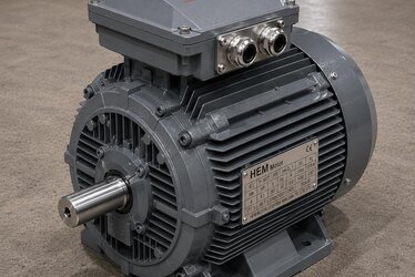
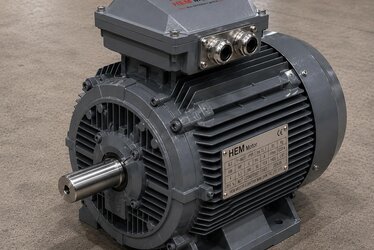
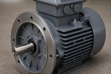
Electric motor mounting types use IEC-standard codes for flanged connections. The B14 flange is a footless, relatively small-diameter flange on the motor's front endshield. Its defining feature is that the holes on the flange are threaded (tapped) holes; the reducer or machine body bolts directly into the motor's flange. There is no need to drill the mating part, and the assembly is made from the front face.
The B5 flange is the opposite: a larger-diameter, footless flange whose holes are clearance (through) holes. The bolt passes through the motor flange and threads into a tapped hole in the mating body. So in B5 the bolts carry the connection load in shear, while in B14 the load is taken into the flange's own threads. This difference dictates both the assembly direction and which reducer body each motor fits. For a detailed comparison of the two types, see our guide on B5 vs B14 mounting type selection for machine builders.
- B14 (small flange): Threaded holes, small diameter, generally in the 56–160L frame range. Common in small and medium-power reducer applications.
- B5 (large flange): Clearance holes, large diameter, up to 63–355L frames. Preferred for heavy-duty and large reducer/pump connections.
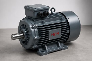
- B34: A footed motor with a small (B14) flange added to its front face; it bolts both to the base via feet and to the reducer via the flange.
- B35: A footed motor with a large (B5) flange added to the front; common at higher powers.
B14 Flange Dimensions: Which Numbers Matter?
A flange dimension is never a single number. When matching a motor to a reducer you must evaluate three core dimensions together. If any one of them does not match, the flange will either not seat at all or seat off-center.
1. Spigot / register diameter — N
The raised or recessed circular face at the center of the flange is the centering spigot. This diameter makes the motor seat perfectly on-axis with the reducer; it centers the shaft. On B14 motors this diameter is standardized by frame size (smaller on a 56 frame, larger on a 90 frame). If the register diameter does not match, the motor shaft and reducer input run with misalignment, which translates directly into vibration and bearing and oil-seal failure.
2. Bolt circle diameter — M
This is the diameter of the circle through the centers of the threaded holes. It defines the bolt spacing and the number of bolts (usually four). The holes in the reducer input flange must match this circle exactly.
3. Flange outer diameter — P
This is the total outer diameter of the flange; it is checked so the flange fits the reducer's mounting face. On B14 this diameter is smaller than on B5, which is why B14 motors fit more compact reducer bodies.
The IEC standard tabulates this N–M–P trio for every frame size. So when you say "71 B14", the reducer manufacturer knows exactly which register, bolt circle and outer diameter to expect. For a correct order you must state not just the motor power but the frame size + flange type combination together.
Shaft and Key: The Part That Enters the Reducer Input
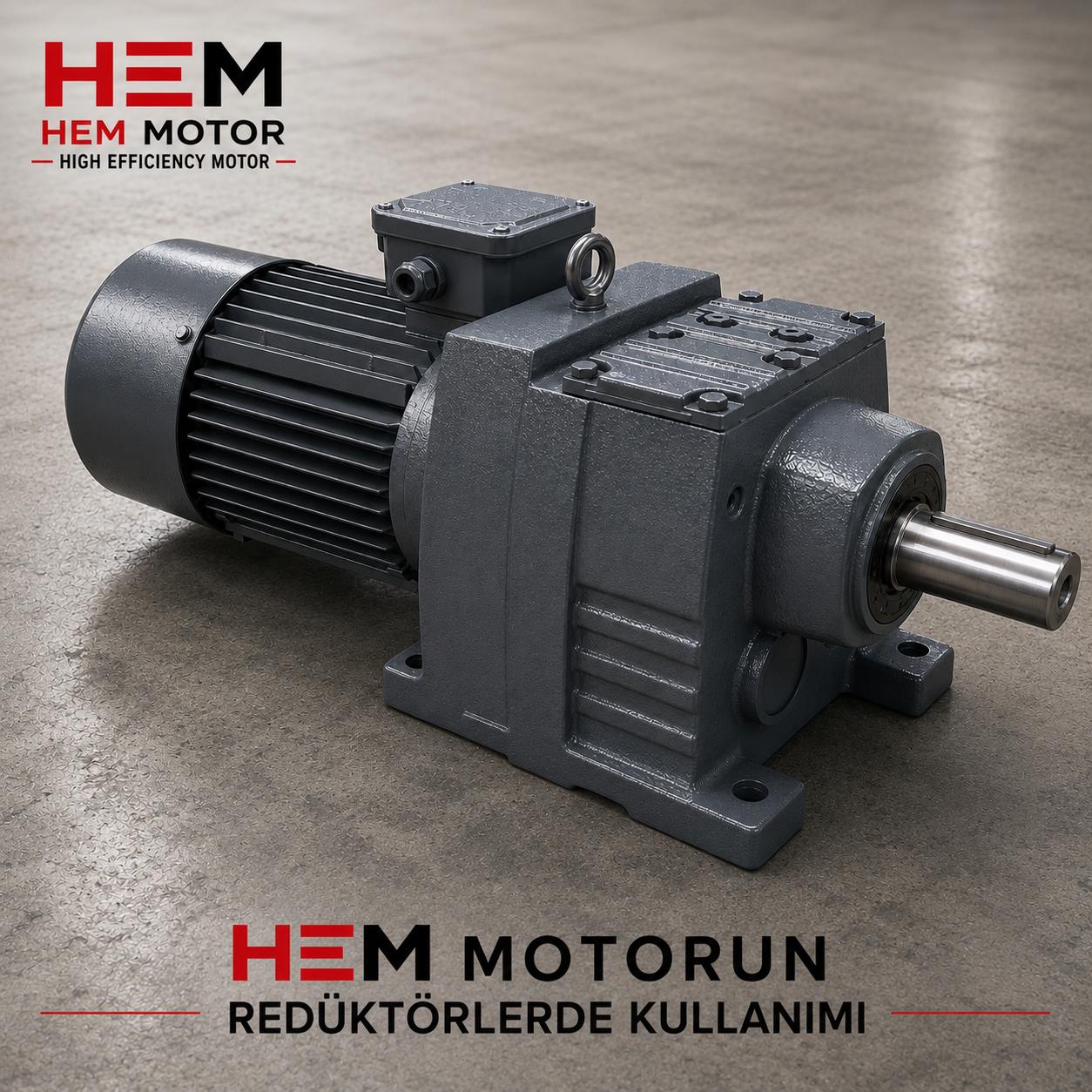
The flange fastens the motor to the reducer, but the shaft is what actually transmits the power. The B14 motor shaft enters the input sleeve of the worm gear reducer (the bore where the worm screw connects). Two dimensions are critical here: shaft diameter and length, plus the keyway on the shaft. The shaft diameter must match the reducer input bore, and the key must be sized correctly to transmit torque without slipping.
IEC frame sizes also standardize shaft diameter (a 71 frame has a specific shaft diameter; a 90 frame a larger one). So even if the flange matches, the connection cannot be made if the shaft diameter does not fit the reducer. In practice HEM reducer bodies are tabulated with the IEC frame and flange combinations they accept; for dimension-level guidance see our reference on matching the right motor to a worm gear and NMRV reducer (IEC frame and flange).
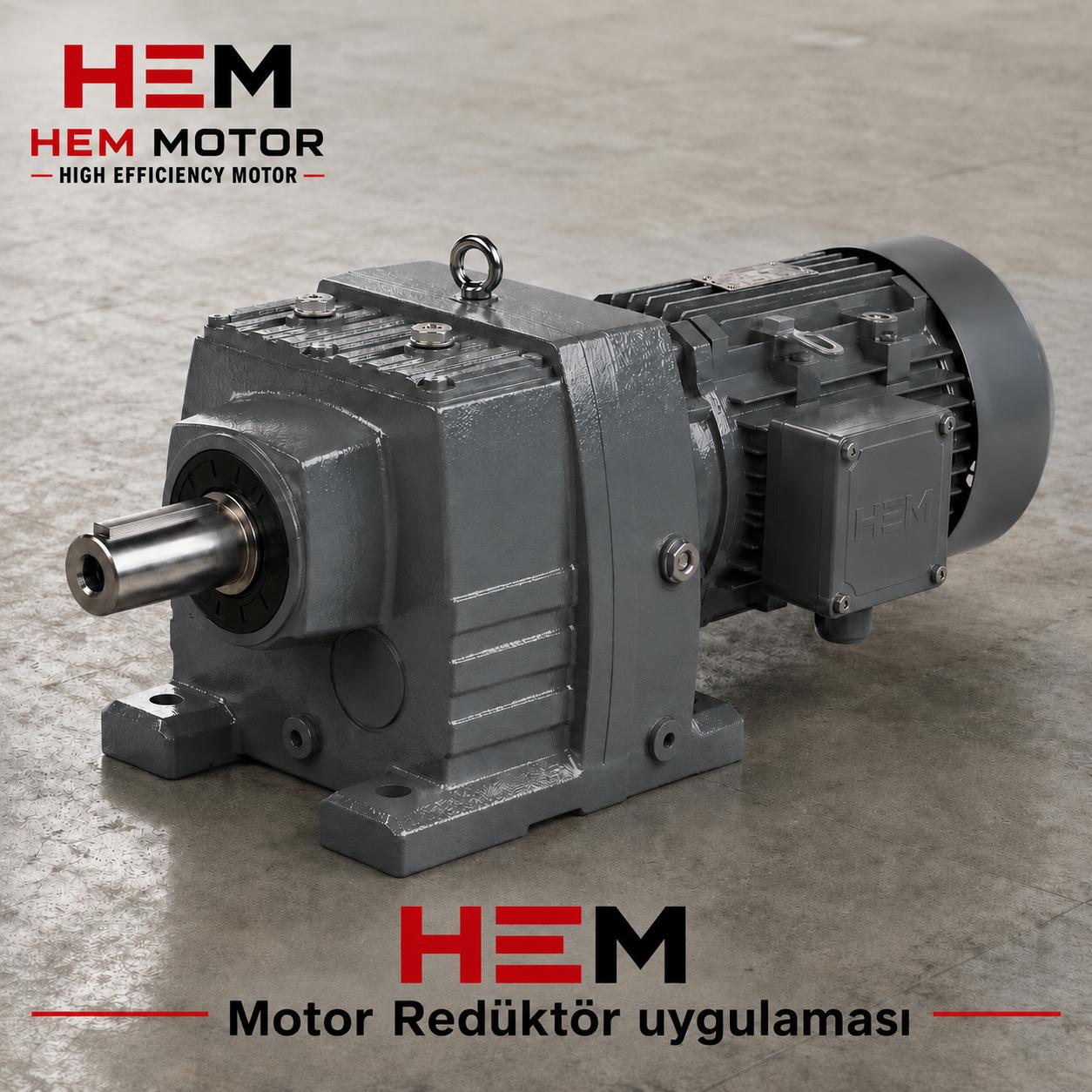
Matching HEM Reducer Bodies with B14 Motors
Worm gear reducer bodies are designed to accept specific IEC motor frames. The practical matching logic for the reducer connection is as follows:
- HEM30 body: 56 B14 and 63 B14 motors — very small power, compact drives.
- HEM40 body: 63 B14 and 71 B14 — light conveyors, dosing, small mixers.
- HEM50 body: 63 / 71 / 80 B14 — common at medium-light loads.
- HEM63 body: 71 / 80 / 90 B14 — general industrial drives.
- HEM75 body: 80 / 90 / 100 B14 — higher-torque applications.
- HEM110 body: 100 / 112 / 132 B14 — medium-to-large drives near heavy duty.
As you can see, each reducer body accepts a specific motor frame range. When you want to fit a larger frame motor, the flange and shaft dimensions change, so the reducer input must also be ordered with the matching adapter/flange for that frame. This is why buying motor and reducer separately, each unaware of the other, often ends in a mismatch. We compare whether it makes more sense to buy them separately or together in our geared motor vs separate motor + reducer comparison.
Why Is Centering So Important?
If the motor shaft and reducer input do not rotate on the same axis (misalignment), a cyclic stress is imposed on the shaft and bearings every revolution. The job of the centering spigot is precisely to prevent this misalignment: the raised register on the flange seats fully into the recess on the reducer, centering and locating the motor relative to the reducer. If the register diameter is too small the motor floats; if it is too large it will not seat at all. In both cases the result is the same:
- High-frequency vibration and noise,
- Premature bearing wear and overheating,
- Stress on the oil seal and oil leakage from the reducer,
- Irregular contact between worm and gear, hence loss of efficiency and life.
In a correctly centered connection, the load is distributed evenly, the system runs quietly, and the high efficiency offered by an IE3 motor is genuinely preserved in the field. Bolting an efficient motor to a poorly centered reducer means giving back the energy you saved through friction and vibration losses.
Where the IE3 Motor Fits in This Picture
The electric motors HEM Motor produces for reducers are IE3 and IE4 efficiency class, with 100% copper windings, F-class insulation and IP55 protection. Aluminum bodies are offered for small and medium-power reducer applications, and cast-iron bodies for heavy-duty and harsh environments. The B14 flange option is especially common on small-power aluminum-body motors (starting from 0.12 kW), because it mates one-to-one with compact reducer bodies.
If you want to review the correct motor family for reducers, our pages list the available frame, power and flange options together, and on the gearbox side our worm gear reducers product group shows the body range from HEM30 to HEM130 and the motor flanges they accept.
Should I Choose B14 or B5?
This decision depends on the application power and the reducer body. A practical summary:
- Small power, compact machine, light load: The B14 small flange is usually sufficient and more economical. Preferred for conveyor dosing, small mixers, packaging machines.
- Medium-to-large power, heavy duty, high torque: The B5 large flange gives a safer connection; large reducer bodies already expect a B5 flange.
- If you need both feet and a flange: Choose B34 (feet + B14) or B35 (feet + B5); the motor bolts both to the floor and to the reducer.
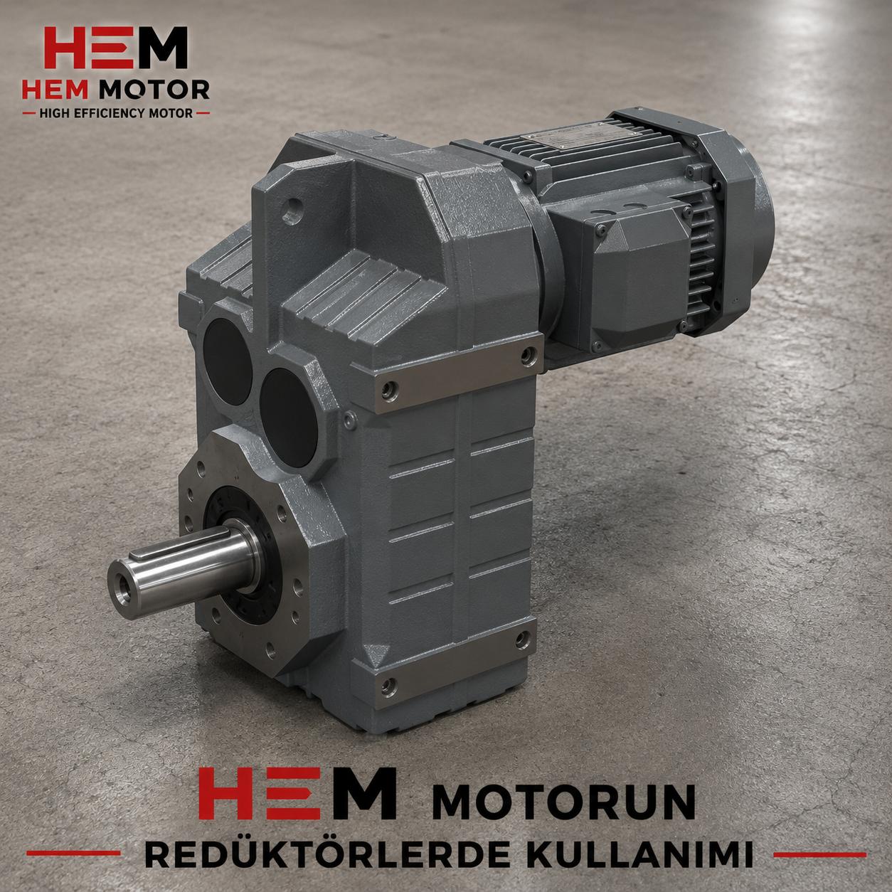
If you need a 90-degree power output, helical-bevel reducers come into play. Bevel-helical bodies also accept specific IEC frame and flange combinations, so the B14/B5 choice must be made with the same care there too.
Information Needed for a Correct Order
The surest way to prevent the wrong motor from arriving is to provide this information completely on the order:
- Power (kW) and speed/pole count — e.g. 0.75 kW, 1500 rpm (4 poles).
- Frame size + flange type — e.g. 80 B14 (saying only "B14" is not enough; the frame size is essential).
- Efficiency class — IE3 or IE4.
- Body material — aluminum or cast iron.
- Reducer body type and reduction ratio — e.g. HEM50, 1/30; so the motor shaft and flange are matched to the reducer input.
- Shaft diameter / key — note any non-standard application.
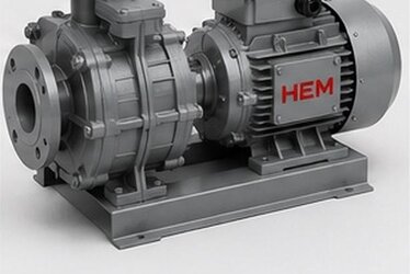
When we receive this information at HEM Motor, we can deliver the motor and reducer matched to each other and, when needed, as an assembled gearmotor. For current models, body options and electric motor prices you can reach us through our homepage; send us your requirement with its dimensions and check stock availability.
Frequently Asked Questions
Can I fit a B5 flange motor instead of a B14 flange motor?
Not directly. The register diameter, bolt circle and hole type (threaded vs clearance) differ between B14 and B5 flanges. If the reducer body is made for a B14 input, a B5 motor will not seat. The solution is either to supply a motor with the correct flange type, or to order the reducer input with an adapter flange for the frame-flange combination you want. The safest approach is to buy the motor and reducer matched together.
If I just say "B14 motor", will the right part arrive?
No. "B14" only states the flange type; the frame size sets the dimensions. A 71 B14 and a 90 B14 have different register diameters, bolt circles and shaft diameters. So you must always specify frame size + flange type (e.g. 80 B14) together with the reducer body it will work with.
What are the symptoms of a poorly centered motor-reducer connection?
The most typical symptoms are increasing vibration and noise during operation, heating on the reducer input side, oil leaking past the seal, and repeated bearing failures over a short period. These usually stem from the motor shaft and reducer input not being on the same axis; disassemble the connection and check that the centering spigot seats fully into the reducer recess.