English
 Türkçe
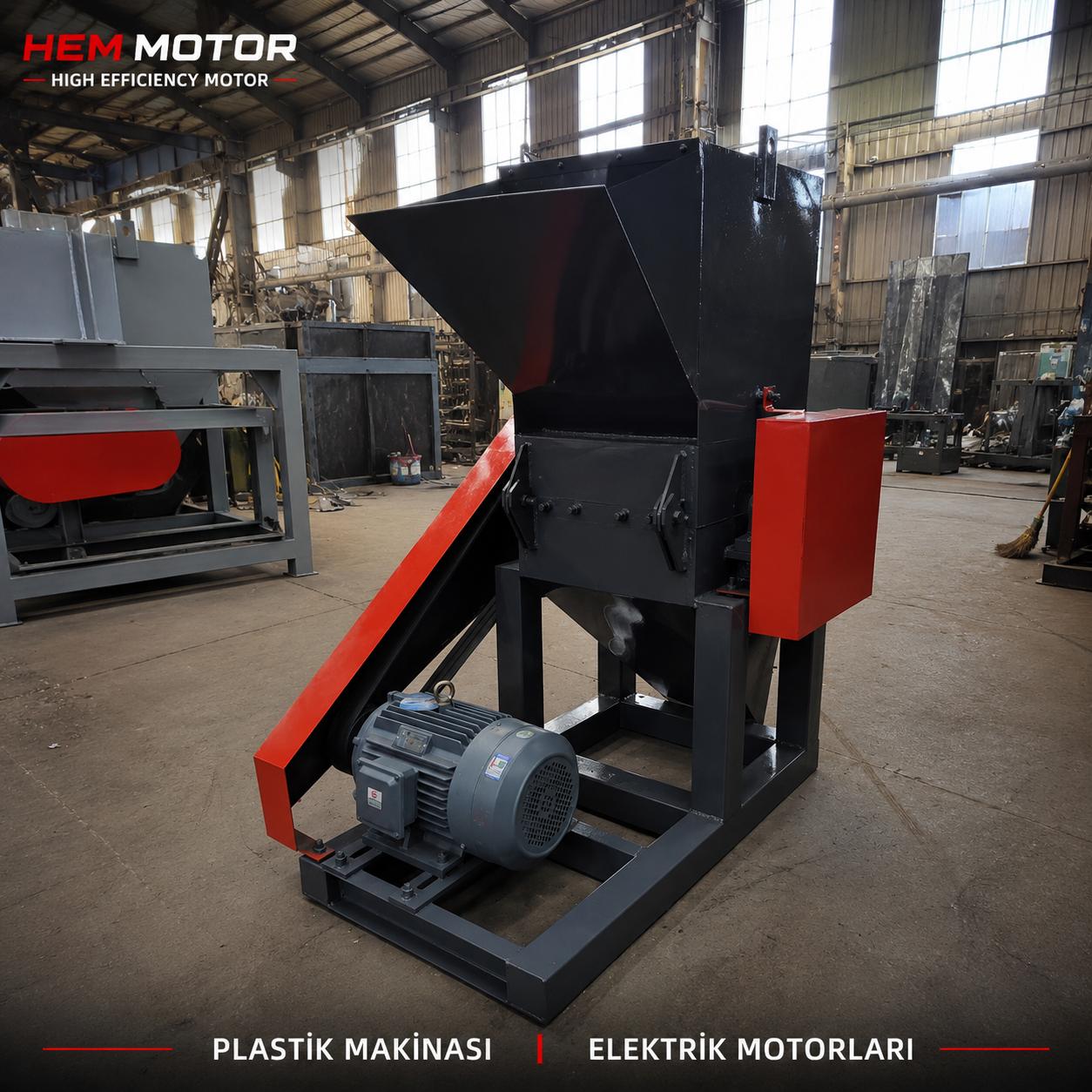
In crusher and mining plants, the ore carried on the feed conveyor frequently contains so-called tramp iron: broken excavator teeth, bucket tips, bolts, nuts, tool fragments and welding rod stubs. When these metals reach a jaw crusher, impact crusher or mill, they seriously damage liner plates, jaws, hammers and the mantle-concave assembly, causing breakdown downtime, lost production and high maintenance costs. The over-band magnetic separator is used precisely to remove these metal pieces from the belt flow and protect the plant. In this article we address not the magnet's own excitation circuit, but the selection of the drive motor that rotates the self-cleaning separator belt: which power, pole count, gearbox, protection class and mounting type are correct on a dusty, high-impact crusher site.
Correct drive motor selection is the foundation of the separator's reliable around-the-clock operation. A wrongly selected motor clogs with dust, overheats or mismatches the gearbox; this lets separated metal accumulate on the belt and re-enter the flow. At HEM Motor we offer cast-iron body, IE3/IE4 efficient drive solutions with IP65/IP66 protection on request, matched to HEM gearboxes for crusher and mining applications. Below we examine separator drive motor selection parameters step by step, give a sample power calculation, and offer a practical crusher motor selection framework for the field.
How an Over-Band Magnetic Separator Works and What the Drive Motor Does
An over-band magnetic separator consists of a powerful magnet suspended perpendicular or parallel above the main conveyor, and a thin belt rotating around that magnet. The magnet pulls iron pieces in the flow upward; in the self-cleaning type, the separator belt rotating around the magnet continuously carries the captured metal sideways and discharges it into a collection chute. The element rotating this separator belt is the drive motor we are selecting. The magnet itself (if an electromagnet) is energized by a separate DC excitation circuit; permanent-magnet types have no magnet supply at all. So motor selection concerns only the mechanical drive of the belt.
The drive belt must rotate at low speed, steadily and continuously. The surface speed is typically in the 1–2.5 m/s range, which requires the motor to deliver output through a gearbox rather than directly. A low-speed drive with high starting torque, running on continuous S1 duty, is needed. Therefore pole count, gear ratio and duty type are evaluated together. For integrity with other plant equipment, keeping the same protection and efficiency standard as the screen and feeder motors is recommended.
Power Range: Why Small-to-Medium Power Is Sufficient
The separator belt is much shorter and lighter than the main conveyor; the load it carries is only the weight of the separated metal, not the entire ore flow. Therefore the drive motor power is usually in the small-to-medium range: typically 0.55 kW to 4 kW. As belt width, separator belt length, magnet weight and required belt speed increase, the power demand rises toward the upper limit of this range. Large separators over wide feed belts (1000–1400 mm) use 2.2–4 kW; narrow belts (500–800 mm) commonly use 0.55–1.5 kW.
The HEM Motor sector series starts at the 0.55 kW lower limit and offers ample power resolution for this application. Always leave a safety margin in power selection; coarse metal accumulating under the separator belt, belt scraper friction and gear oil thickening in cold weather all increase the starting torque. Rounding the calculated power up to the next standard kW step is therefore the correct approach. For the relationship between power and efficiency class, we recommend the IE4 motor and gearbox combination review.
Pole Count and Speed: The Low-Speed Drive Logic
Because the required separator belt surface speed is low, running the motor at low speed keeps the gear ratio reasonable. Two common approaches exist:
- 4-pole motor (≈1500 rpm, 1460 under load): Smaller frame, lower cost; but reaching the low output speed requires a higher gear ratio.
- 6-pole motor (≈1000 rpm, 960 under load): The lower input speed reduces the gear ratio, the output torque settles more smoothly, and it is advantageous for heating in continuous low-speed use.
In this application requiring continuous low speed and constant torque, 6-pole (and in some cases 8-pole) motors may be preferred. To understand the advantages and constraints of low-speed motor selection in depth, our asynchronous 6-8 pole low-speed motor selection article is a good start. On many separators a 4-pole motor plus a suitably geared reducer is also a practical and economical solution; the decision is made according to gear ratio and available stock frames.
Gearbox Selection: Worm or Helical Bevel?
In over-band separator drives the motor is almost always used with a gearbox because the output speed is not 1500 or 1000 rpm but in the order of tens of rpm. Two main gearbox families stand out:
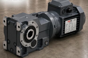
HEM Worm Gearbox
With its compact structure, 90-degree output shaft and ability to provide high reduction ratios in a single stage, it is a very common solution for separator drives. HEM worm gearbox ratios range from 1/7.5 to 1/100, allowing very low output speeds in a single stage. The frame-to-power matching is: HEM50 (0.18–0.75 kW), HEM63 (0.37–1.5 kW), HEM75 (0.75–3 kW), HEM110 (2.2–7.5 kW). Separator powers mostly fall into this HEM50–HEM110 range. The worm gearbox also features self-locking, preventing the belt from sliding back when stopped, so collected metal does not spill into the flow.
K Series Helical Bevel Gearbox
For larger separators requiring higher efficiency and higher torque transmission, the K series helical bevel gearbox is preferred. Being more efficient than the worm gear, it is advantageous in energy consumption during continuous operation. Which gearbox type to choose depends on belt size, required speed and duty duration. For correctly establishing the mechanical connection between gearbox and motor, our flexible/rigid coupling selection and shaft alignment guide helps you avoid mounting errors. For efficiency and selection details of geared drives, you can review our electric motors product family.
Protection Class: IP65/IP66 Is Essential in Dusty Environments
A crusher and mine plant is one of the harshest environments for an electric motor: heavy dust, stone fragments, metal splash, water washing and vibration all combine. While standard IP55 protection is sufficient for many general applications, because the separator drive motor runs continuously under a dust cloud, IP65 or IP66 on request is recommended. IP65 provides full dust-tightness and resistance to low-pressure water jets; IP66 provides protection against powerful water jets. If dust enters, winding temperature rises, bearing life shortens and insulation degrades.
The HEM Motor sector series offers IP55 as standard and is manufactured in IP65/IP66 on request. We covered in detail why dust sealing is critical on a crusher site in our crusher motor dust sealing IP65/66 field article. You can learn the logic of choosing the right protection class in general from our electric motor IP protection class selection guide.
Body Material and Insulation Class
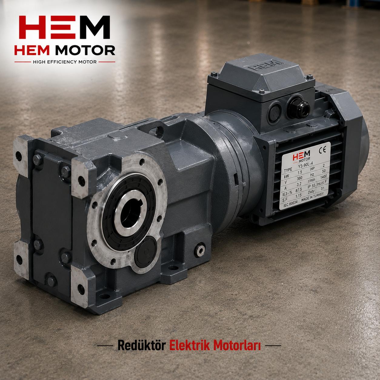
Because the separator drive motor operates near the magnet and in a continuous impact-and-dust environment, it requires a mechanically robust body. A cast-iron body offers higher impact resistance, better vibration damping and longer life than aluminium; therefore cast iron is preferred in heavy-duty crusher applications. HEM Motor manufactures cast-iron body motors with F class insulation and 100% copper windings.
In hot, dusty environments, choosing the correct insulation class directly affects the thermal life of the winding. F class insulation (155 °C) is standard; at points with very high ambient temperature or heavy dust accumulation, an upgrade to H class may be considered. We detailed this topic in our hot and dusty environment motor insulation class (cast iron) article. You can reach our entire cast-iron body motor family from the crusher and stone crushing motors blog category.
Mounting Type Selection
The separator drive motor is fixed to the separator chassis together with the gearbox. The mounting is chosen according to gearbox type and connection method:
- B5 (large flange): The most common choice for direct flanged connection to the gearbox; motor and gearbox combine compactly on a single axis.
- B14 (small flange): Available only in the 56–160L frame range; provides compact gearbox connection in low-power separator drives.
- B35 (foot + large flange): Used in mountings needing both a flange connection and foot support, where extra security is desired on vibrating sites.
- B3 (foot-mounted): Preferred when a separate gearbox is connected via belt-pulley or coupling.
In most geared-motor (motoreducer) solutions, a B5 or B14 flanged motor seats directly on the gearbox input, eliminating the need for a coupling and thus reducing the risk of alignment error.
Sample Power and Gearbox Calculation
Consider a self-cleaning separator placed over a 1000 mm feed belt. Let the separator belt surface speed be 1.5 m/s and the drive drum diameter about 0.2 m. The drum circumference is π × 0.2 ≈ 0.628 m; the required drum speed = 1.5 / 0.628 ≈ 2.39 rev/s ≈ 143 rpm. If we use a 6-pole motor (≈960 rpm under load), the required gear ratio ≈ 960 / 143 ≈ 1/6.7; in practice a 1/7.5 standard ratio is chosen and the speed slightly reduced. If a 4-pole motor (≈1460 rpm) is used, the ratio ≈ 1460 / 143 ≈ 1/10.2; the HEM worm gearbox 1/10 standard ratio fits this need.
On the power side: since the load on the separator belt is light, the mechanical power demand is generally in the order of 0.5–1.5 kW. Adding starting torque, scraper friction and a safety margin, choosing a standard step such as 1.1 or 1.5 kW is safe. This power matches the HEM63 (0.37–1.5 kW) or HEM75 (0.75–3 kW) gearbox frame. On larger separators, 2.2–4 kW and the HEM110 frame come into play. You can find the supply logic of high-torque mine drives in our mine ore mill motor high torque supply article, and heavy feeder drives in our mine apron chain feeder drive motor selection article.
Continuous Duty (S1), Cooling and Bearing Life
The separator usually rotates continuously as long as the plant is running; therefore the motor must be sized for S1 continuous duty. In low-speed 6/8-pole motors, internal fan cooling is weaker than in high-speed ones; heating must be watched at full load and high ambient temperature. If dust accumulation between the body fins blocks cooling, the temperature rises rapidly, so periodic cleaning is essential. We addressed motor heating and full-load behaviour in our crusher motor cooling and overheating article.
Impact, vibration and dust directly shorten bearing life. In the separator drive, continuous low speed and the impact of falling metal pieces stress the bearing; therefore suitable bearing clearance, quality grease and dust seals are important. We detailed the factors affecting bearing life in our crusher and mill motor bearing life (shock and dust) article. For general motor protection and field maintenance, our stone quarry and mine motor protection article is complementary.
Efficiency and Regulation
For a continuously running drive, efficiency class is directly an energy cost. Under Ecodesign 2019/1781, since July 2021 at least IE3 has been mandatory for DOL three-phase motors between 0.75–1000 kW; for 0.12–0.75 kW motors there is an IE2 requirement. Since separator drive motors are mostly in the 0.55–4 kW range, the IE3 lower limit must be met for options of 0.75 kW and above, and IE4 Super Premium should be preferred where possible. Moving to IE4 on continuously running equipment pays back the energy saving quickly because the annual running hours are high.
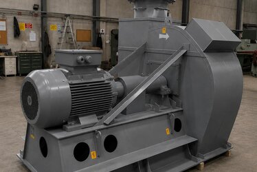
The HEM Motor IE4 series starts from 0.25 kW and, with its cast-iron body, IP55 (IP65/IP66 on request) and F class insulation, suits this application. For efficient and sector-specific motor options, you can visit our IE4 motors product page and our HEM Motor home page. For aspirator and dust-collection fan drives operating in dusty environments, also see our aspirator and dust collection fan motor selection article. For plant-wide cement and mining equipment motors, our cement factory electric motors content is also a useful guide.
Wet and Semi-Wet Environment Note
In some plants the separator works near an aggregate washing line or above a moist ore flow. At points with water splash, IP66 protection and, if necessary, stainless fasteners are recommended. We shared the selection logic for wet-environment drive motors in our aggregate washing sand screw motor selection article.
Frequently Asked Questions
How many kW should a magnetic separator drive motor be?
Because the load carried by the separator belt is only the separated metal, the power demand is small-to-medium; the typical range is 0.55–4 kW. Narrow belts commonly use 0.55–1.5 kW, wide belts 2.2–4 kW. For the exact value, it is best to request a quote by sharing belt width, separator belt speed and magnet size.
Why is a geared motor always used?
The separator belt surface speed is a low value such as 1–2.5 m/s, which brings the drum speed down to hundreds of rpm. A gearbox is essential to reduce the motor's 1500 or 1000 rpm to this level. A HEM worm gearbox (1/7.5–1/100) or a K series helical bevel gearbox is used for this; the worm gear's self-locking feature also prevents the belt from sliding back.
Which IP class is needed in a dusty crusher environment?
Although standard IP55 is sufficient for many applications, since the separator runs continuously under a dust cloud, IP65 or IP66 is recommended. IP65 provides full dust-tightness and resistance to low-pressure water jets, while IP66 withstands powerful water jets. HEM Motor produces these classes on request.
Get a Quote
Let us clarify the over-band magnetic separator drive motor selection for your crusher and mine plant. Share the belt width, separator belt speed, magnet type and ambient conditions; together we will determine the suitable power, pole count, gear ratio and protection class. To get a quote right away, call us at +90 (532) 345 49 86 or reach us through our contact page. You can review all our electric motors and geared drive solutions.
Selection Checklist
- Are the feed belt width and separator belt length determined?
- Is the required separator belt surface speed (m/s) defined?
- Are the required output speed and gear ratio calculated from the drum diameter?
- Is the pole count (4/6/8) chosen according to duty type?
- Is the power rounded up to the next standard kW step (safety margin)?
- Are the gearbox type (HEM worm or K helical bevel) and frame matched?
- If self-locking is required, is a worm gearbox selected?
- Is protection class requested as IP65/IP66?
- Are the cast-iron body and F (or H if needed) insulation class verified?
- Is the motor sized for S1 continuous duty?
- Is the mounting type (B5/B14/B35/B3) chosen to suit the gearbox?
- Is the efficiency class IE3/IE4 compliant with regulation?
- Are dust cleaning and bearing maintenance planned?
- If there is a wet point, are IP66 and suitable fasteners planned?