English
 Türkçe

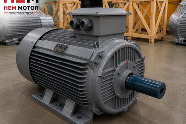
When replacing a cast iron framed motor or coupling it to a drive, the most frequently overlooked yet most critical dimension is the shaft height, that is the H dimension. The H dimension is the perpendicular distance from the shaft centerline to the foot mounting surface, and it is the value that defines the frame size in the IEC standard: H 56 mm on an IEC 56 frame, H 132 mm on an IEC 132 frame, H 355 mm on an IEC 355 frame. If this dimension does not match, the driven machine shaft and the motor shaft do not align on the same axis; the coupling is stressed, the belt-pulley alignment breaks down, and the bearings fail early. In this guide we cover what the H dimension is, why the same H is required in replacement, how axial alignment is achieved in coupling and belt mounting, and the problems caused by choosing the wrong H. This article is different from the shaft diameter and frame table; here the focus is on the height of the shaft centerline and axial alignment.
What Is the H Dimension (Shaft Height)?
The H dimension is the perpendicular height from the motor foot base (mounting surface) to the shaft center. The IEC 60072 standard makes this height the name of the frame size: 56, 63, 71, 80, 90, 100, 112, 132, 160, 180, 200, 225, 250, 280, 315, 355 mm. So when a motor is 'frame 132', it means the shaft centerline is 132 mm above the foot base. This height lets the machine or base the motor is mounted on meet the driven element on the same axis. The rigidity of the cast iron frame keeps this height tolerance from degrading over time; we covered the impact and rigidity advantage of the cast iron frame in our impact resistance and rigidity in cast iron frame article.
The H dimension should be evaluated together with our cast iron frame size and power matching article showing the frame-power match and our IEC 56-355 frame sizes article giving frame sizes by weight.
Why Is the H Dimension Different from the Shaft Diameter?
The shaft diameter is the thickness of the shaft on which the coupling or pulley sits; the H dimension is the height of the shaft from the ground. Two motors may have the same shaft diameter but a different H dimension, or vice versa. When replacing, both dimensions must be checked separately. We detailed shaft diameter, key and coupling matching in our shaft diameter, key and coupling on cast iron motor article and shaft dimensions for coupling and pulley compatibility in our motor shaft diameter and key dimensions content. The focus of this article is different: at what height the shaft rotates and its alignment with the machine.
Why Is the Same H Dimension Required in Replacement?
If you are replacing a motor on the same base, the H dimension of the new motor must match the old one exactly. Otherwise the shaft centerline shifts up or down from the machine drive axis. For example, if you fit a frame 160 instead of a frame 132, the shaft rises 28 mm and the coupling never aligns. If the H dimension does not match, either the base must be machined, compensated with shims, or the correct frame must be selected. We explained the importance of exact matching in replacement in our direct replacement of old brand motor and frame, foot and shaft compatibility in IE4 transition articles. You can find the emergency replacement checklist for critical replacements such as conveyor motors in our conveyor belt motor emergency replacement content.
Axial Alignment in the Coupling and the Role of the H Dimension
The coupling is the element that connects two shafts, and for it to work correctly the two shafts must be on the same axis. Misalignment is of two kinds: parallel offset (two axes parallel but shifted horizontally/vertically) and angular offset (axes at an angle to each other). If the H dimension is not correct, a vertical parallel offset occurs; the motor shaft height differs from the machine shaft. This offset creates vibration and early wear even in a flexible coupling, and directly stresses the shafts and bearings in a rigid coupling. We covered flexible versus rigid coupling selection and shaft alignment in detail in our flexible vs rigid coupling selection and shaft alignment article. You can find the vibration limit values in our ISO 10816 vibration and balance content.
Shims and Height Adjustment
Small differences in the H dimension or ground unevenness are compensated with thin adjustment plates called shims. By placing measured shims under the motor feet, the shaft centerline is brought to the machine axis. However shim compensation is only for small differences; a whole frame size difference (e.g. 160 instead of 132) cannot be corrected with shims, the correct H-dimension motor is required. Using a laser alignment tool or dial indicator gives a much more accurate result than rough eyeballing. We collected the pre-mounting mechanical checks in our commissioning and first startup checklist article.
The H Dimension in Belt-Pulley Drives
The H dimension is also important in belt-pulley drives, because the two pulleys must be in the same plane and the belt alignment must be correct. If the motor shaft is at a different height from the machine shaft, the belt runs at an angle, wears at the edge and breaks early. We explained selecting the motor speed together with pulley diameter and belt tension in our V-belt-pulley drive motor selection and motor speed and pulley-belt ratio articles. The rigidity of the cast iron frame is an advantage in carrying the radial loads that occur in belt drives.
Problems Caused by the Wrong H Dimension
A motor with the wrong H dimension causes misalignment in mounting, vibration in operation, early bearing failure and rapid coupling/belt wear. As vibration increases, so does noise; correct alignment is essential for low-vibration operation. We covered noise and vibration sources in our noise and vibration, low-noise motor selection and noise sources in asynchronous motors articles. You can find the early failure causes and the effect of misalignment on bearing life in our motor life and early failure causes content.
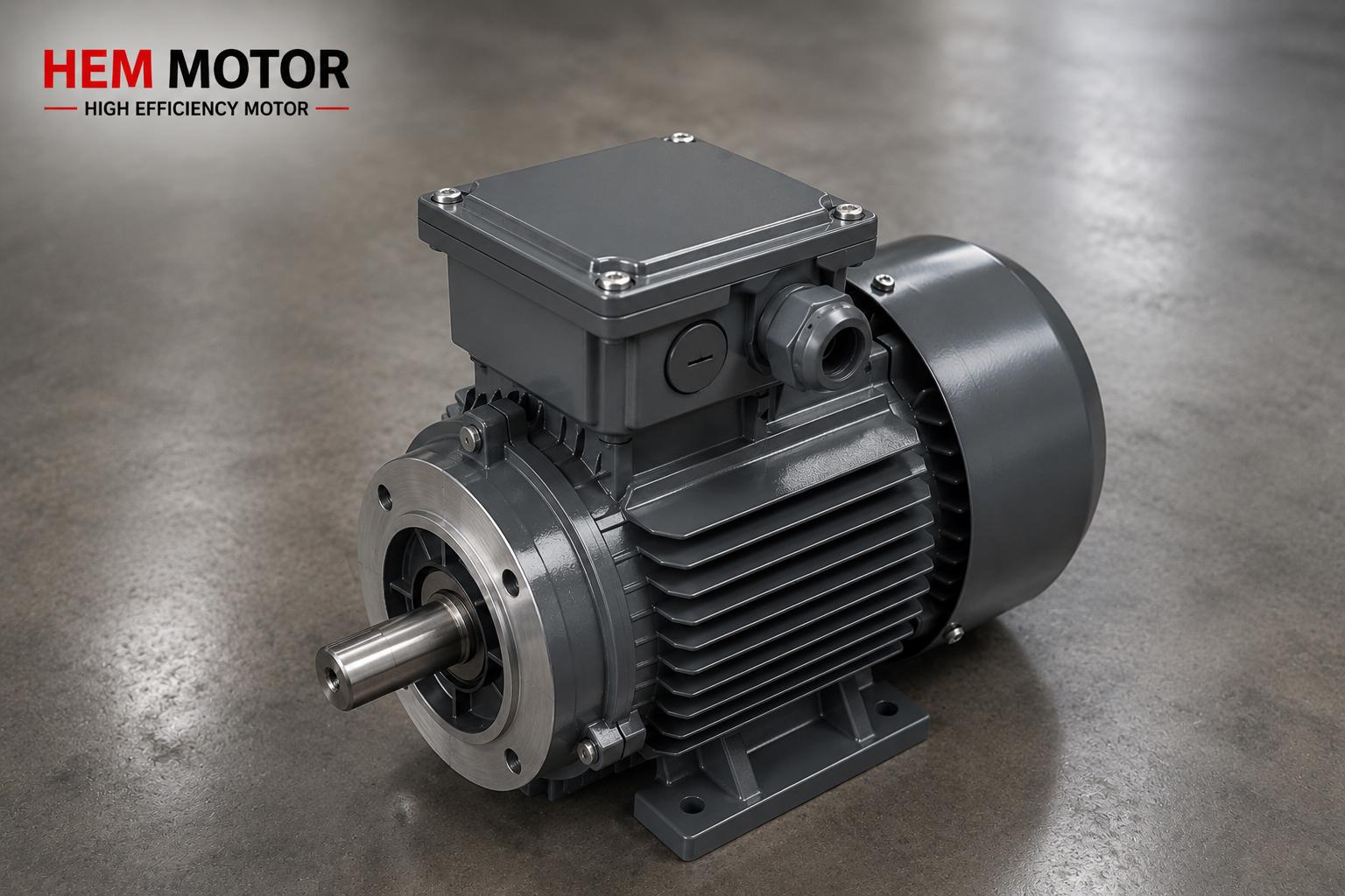
The Situation Is Different in Flange Mounting
In B5 or B14 flange-mounted motors, the flange diameter and hole distribution are decisive instead of the H dimension, because the motor is mounted from its flange, not its foot. If the motor you are replacing is flange-mounted (B5/B14) rather than foot-mounted (B3), this time the flange dimensions, not H, must match. We detailed the flange type and hole dimensions in our flange type and hole dimensions on cast iron motor and B5 vs B14 mounting type selection articles. In B35 (foot + flange) mounting, both H and flange dimensions must match together.
Foot Hole Axial Distance and Frame Length Code (S/M/L)
While the H dimension gives the shaft height, the axial distance of the motor foot holes is determined by the frame length code (S, M, L). At the same H dimension (for example 132S and 132M) the foot holes may be at different spacing; this is critical for the bolt holes to fit the base. When replacing, you must verify not only H but also this length code and the foot hole center distances. Otherwise, even if the shaft height is correct, the foot holes will not sit on the existing holes in the base. We covered frame sizes and the dimensional relationship in our IEC 56-355 frame sizes and machining tolerance of the frame in our frame machining, tolerance and concentricity articles.
The Effect of Wrong Alignment on Bearing Life
In a motor with an unmatched H dimension or broken axial alignment, the bearings are subjected to radial and axial forces they were not designed for. This significantly shortens bearing life; vibration increases, temperature rises, and the bearing eventually fails early. Correct alignment also preserves grease life and housing durability. We covered bearing greasing and the lubrication interval in our bearing greasing, grease type and interval, temperature monitoring in our PT100 and thermistor temperature monitoring, and vibration balance acceptance values in our ISO 10816 vibration and balance articles. The investment in alignment is far below the cost of bearing and coupling replacement.
Frequently Asked Questions
Is the H dimension the same thing as the frame size?
Yes, in the IEC standard the frame size number directly gives the H dimension (shaft height in mm). 'Frame 132' means the H dimension is 132 mm. However there may be frame length variants such as S, M, L at the same H dimension; these variants change not H but the axial distance of the foot holes and the motor length. In replacement, both H and this length code may be important.
The H dimension does not match in replacement, what can I do?
If the difference is small (a few mm), you can compensate by adding shims under the motor feet. If the difference is as large as a frame size (e.g. 160 instead of 132), shims will not solve it; you must either machine the base or supply a motor with the correct H dimension. The healthiest approach is to select a motor with the same H dimension from the start; you can find ways to request a quote with the correct information in our information to give when requesting a quote article.
Can I do the axial alignment by eye?
In small and low-speed applications, rough alignment with a ruler and square works to some extent, but in high-speed or critical drives a dial indicator or laser alignment tool is essential. An incorrectly aligned coupling seriously shortens bearing life and creates vibration. You can find the alignment and mounting steps in our coupling selection and shaft alignment article.
Get a Quote
Consult our team to supply a cast iron motor that fits your existing base and coupling exactly, with the correct H dimension (shaft height) and frame size. When you tell us the frame size, shaft diameter and mounting type of the existing motor, we quickly find the correct motor that will fit without breaking the axis alignment. You can reach us at +90 (532) 345 49 86 or request a quote through our contact page. You can review the full range from our homepage and the cast iron options from our cast iron vs aluminum frame article.
Purchasing and Mounting Checklist
- Was the H dimension (frame size) of the existing motor determined?
- Is the H dimension of the new motor exactly the same as the old one?
- Were the shaft diameter and key dimensions also checked?
- Were the coupling type (flexible/rigid) and axial alignment planned?
- Are shims ready if required?
- Are the two pulleys in the same plane in belt-pulley drives?
- If it is a flange-mounted motor, do the flange diameter and hole distribution match?
- Was a dial indicator/laser tool obtained for alignment?