English
 Türkçe
A motor being "high efficiency" is much more than an efficiency percentage written in a catalogue; real efficiency is understood by knowing where the losses inside the motor arise and how much each design improvement reduces which loss. A small but significant portion of the electrical power drawn from the grid turns into heat without reaching the shaft; the sum of these losses determines the motor's efficiency. Dividing these losses into five main items and seeing the percentage of each, that is, producing a loss map and efficiency budget, is the only correct way to understand what really improves when moving from IE3 to IE4 and IE5 and how much you will save in the field. In this article, as HEM Motor, we cover the five loss items in high-efficiency motors, the typical share of each, which loss decreases as the efficiency class rises, and how to see the real saving.
Where Do Losses in a Motor Arise?
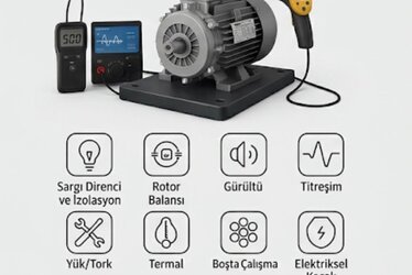
In an asynchronous motor, the difference between the electrical power drawn and the mechanical power delivered to the shaft is the sum of the losses. These losses arise physically in different places and by different mechanisms. The IEC 60034-2-1 standard defines methods to measure these losses and document efficiency. Correctly separating the losses is essential to understand a manufacturer's efficiency claim and to fairly compare different efficiency classes. The losses are divided into five main items: stator copper loss, rotor loss, iron (core) loss, friction and windage (mechanical) loss, and stray load losses.
To see how efficiency is measured and how the nameplate efficiency is documented, our article How Is Efficiency Measured? IEC 60034-2-1 Test Method helps; to verify the nameplate efficiency in the field, Efficiency Value and IE Code on the Nameplate is a basic resource.
The Five Loss Items and Their Typical Percentages
The table below shows the approximate share of the five loss items at full load in a typical medium-power asynchronous motor. These percentages vary with power, pole number and design; but seeing the general distribution lets you understand which item, when improved, will make the most difference.
| Loss Item | Typical Share of Total Loss | Source |
|---|---|---|
| Stator copper loss | 30-50% | Winding resistance, I²R heating |
| Rotor loss | 18-25% | Rotor bar I²R, slip |
| Iron (core) loss | 15-25% | Hysteresis and eddy currents |
| Friction and windage | 8-12% | Bearing, fan, air friction |
| Stray load losses | 5-15% | Harmonic flux, leakage fields |
As seen, the largest item is usually the stator copper loss; therefore the most noticeable improvement in high-efficiency motors is using more and more conductive winding copper.
Knowing Each Loss Item Closely
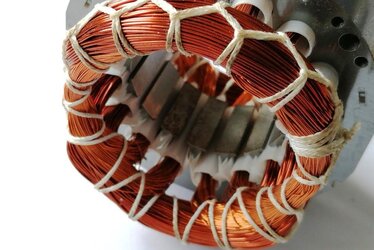
- Stator copper loss: The current through the winding turning into heat in the winding resistance (I²R). Using thicker and purer copper and increasing the slot fill factor reduces this loss. The copper-aluminium winding difference is decisive here.
- Rotor loss: The induced current through the rotor bars turning into heat. A copper rotor bar reduces this loss compared with aluminium die-casting.
- Iron (core) loss: The varying magnetic field creating hysteresis and eddy currents in the core lamination. Using thin and low-loss silicon steel lowers this loss.
- Friction and windage loss: Bearing friction and the cooling fan moving air. Low-friction bearings and an optimised fan design reduce this loss.
- Stray load losses: Arising from non-ideal flux distribution, harmonics and leakage fields, this is the hardest item to measure.
For the effect of the copper and aluminium winding difference on efficiency, our article Copper Winding versus Aluminium Winding Difference helps; for the effect of rotor bar material on efficiency and starting, Rotor Bar Material: Copper or Aluminium Die-Cast? is directly relevant.
From IE3 to IE4 and IE5: Which Loss Decreases?
As the efficiency class rises, losses decrease overall; but at each class transition different items improve to different degrees. In the IE3 to IE4 transition, the biggest gain comes from reducing the stator copper and rotor losses: more copper, better core steel and a lower-loss rotor. In an IE5 synchronous reluctance motor the rotor loss almost disappears, because there is no current-carrying bar in the rotor and no slip loss occurs. This explains why IE5 is so superior, especially at part load.
| Transition | Most Reduced Loss | Mechanism |
|---|---|---|
| IE3 → IE4 | Stator copper, iron | More copper, low-loss steel |
| IE4 → IE5 (SynRM) | Rotor loss | Magnet-free, bar-free rotor; no slip |
To see in detail where iron, copper and friction losses decrease in an IE4 motor, our article Efficiency Losses in an IE4 Motor helps; for IE5's part-load efficiency superiority, Efficiency Curve: Why Superior at Part Load? is the ideal continuation.
Turning the Efficiency Budget Into Real Savings
The real value of loss mapping is being able to turn the on-paper efficiency difference into real money saved. A motor's annual energy cost depends on its power, running hours, load ratio and efficiency. On a motor running continuously and at full load, even a small efficiency difference creates an energy difference over the years that multiplies the motor's purchase price, because the energy cost makes up the vast majority of the total lifetime cost. By contrast, on a motor running only a few hours a day, the same efficiency difference corresponds to a much smaller saving and the extra cost of the higher-class motor is paid back over a long time.
- Running hours: The longer it runs, the more valuable the efficiency difference.
- Load ratio: IE5's superiority becomes pronounced on a motor running at part load.
- Power: Since the absolute loss is large on a high-power motor, the saving is more concrete.
- Energy unit cost: As the cost rises, the payback time of high efficiency shortens.
To see which efficiency class is really cheaper through total cost of ownership, our article IE5, IE4 and IE3 TCO Comparison helps; to see how oversizing eats the saving at low load, Part and Low-Load Efficiency is a direct decision-support resource.
Losses Turning Into Heat and the Role of Cooling
Every loss item in the motor ultimately appears as heat; therefore loss mapping is also a heat map. Stator copper loss produces heat in the winding, iron loss in the core, friction loss in the bearings and fan. A high-efficiency motor, producing fewer losses, heats up less; this means a lower winding temperature, longer insulation life and more reliable operation. Conversely, in a motor where losses accumulate with insufficient cooling, the winding temperature rises and every 10°C increase roughly halves the insulation life. For this reason, high efficiency, a good insulation class (F/H) and effective cooling complement each other: low loss, low heat; low heat, long life.
For the relationship of insulation and thermal class with temperature rise and life, our article Insulation and Thermal Class (F/H) and Temperature Rise helps; for the effect of cooling and fan design on efficiency, The Effect of Cooling and Fan Design on Efficiency is directly relevant. To monitor winding temperature with PT100/PTC, see Winding Temperature Monitoring.
Behaviour of Losses at Part Load
The loss items change with load in different ways; this is the most overlooked aspect of correct motor selection. Iron loss and friction-windage loss are almost independent of load; they exist even while the motor turns at no load. Copper losses (stator and rotor) increase with the square of the current; that is, they grow quickly as the load increases and shrink quickly as it decreases. Therefore, in a motor running at low load, the constant iron and mechanical losses become dominant in the total and the efficiency drops. An oversized motor, i.e. one running continuously at low load, thus cannot reach its nameplate high efficiency in the field. This is exactly where the part-load superiority of the IE5 synchronous reluctance motor becomes pronounced: with no rotor loss, its efficiency curve stays much flatter at part load.
| Loss Item | Variation With Load | Effect at Low Load |
|---|---|---|
| Stator copper | With current squared (I²) | Decreases markedly |
| Rotor | Increases with load | Decreases (absent in SynRM) |
| Iron (core) | Independent of load | Stays constant, dominates |
| Friction-windage | Independent of load | Stays constant |
To see how oversizing lowers efficiency at low load and find the correct sizing, our article Part and Low-Load Efficiency helps; for the decision to stay with IE3 or move to IE4, Stay With IE3 or Move to IE4? is valuable.
Testing the Manufacturer's Efficiency Claim With the Loss Budget
A practical benefit of understanding loss mapping is being able to critically test the manufacturer's efficiency claim. Two motors may carry the same IE class; but one may have reduced its losses by increasing the winding copper, the other only by improving the core steel. These differences change how the motor behaves under load, how much it heats and its part-load efficiency. A good manufacturer shares the loss breakdown and the test report on request; this lets you see the real engineering behind the motor's on-paper class. Especially on high-power, continuously running motors, asking for the loss distribution instead of looking only at the IE class is the most reliable way to distinguish a truly quality motor. Of two motors in the same class, the one with lower copper loss runs cooler in the field and lasts longer. To see the efficiency class mandate and which class is required at which power, our article Efficiency Class Mandate is a direct resource.
Frequently Asked Questions
Which is the largest loss item in a motor?
In a typical asynchronous motor the largest item is usually the stator copper loss (about 30-50% of the total loss). That is why the most noticeable improvement in high-efficiency motors is using more and more conductive winding copper.
Which loss disappears in an IE5 synchronous reluctance motor?
Since there is no current-carrying bar in the IE5 synchronous reluctance rotor, the rotor loss almost disappears and no slip loss occurs. This is the fundamental reason IE5 offers superior efficiency, especially at part load.
Does the efficiency difference give the same saving in every application?
No. The saving depends on running hours, load ratio, power and energy unit cost. The efficiency difference is very valuable on a motor running continuously at high load; on a motor running a few hours a day the payback is longer.
Determine the Right Efficiency Class for Your Budget
As HEM Motor, we evaluate loss mapping and the efficiency budget together with you according to your application's running hours, load ratio and power, and objectively show which of IE3, IE4 or IE5 will deliver the real saving. Share your motor's power, speed and operating profile; let us determine the most suitable efficiency class for you and provide a tailored quote for fast delivery from manufacturer stock so you can source both the right and the economical motor with confidence. Contact us to request a quote.