English
 Türkçe
The most easily overlooked yet most vital connection of an electric motor is not the phase leads; it is the protective conductor. The protective conductor (PE) protects people from electric shock by carrying the dangerous voltage that would appear on the frame during an insulation fault safely to ground, and it enables the protective device (fuse/breaker) to open the circuit. A PE terminal that is not connected correctly carries a silent danger even while the motor runs smoothly. In this article we explain, in field-practical terms, the position of the PE grounding terminal inside the terminal box and outside the frame on a motor, the choice of cross-section and bolt size, the logic of equipotential bonding, high-frequency grounding in VFD systems (shield / 360°), and why grounding at two points is required.
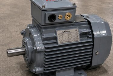
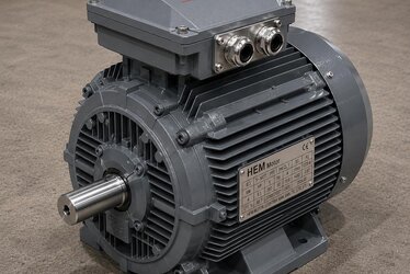
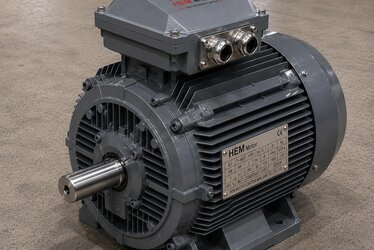
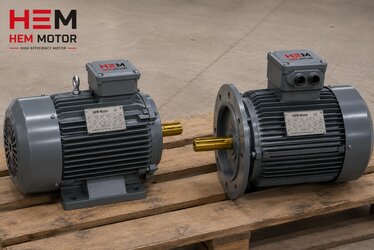
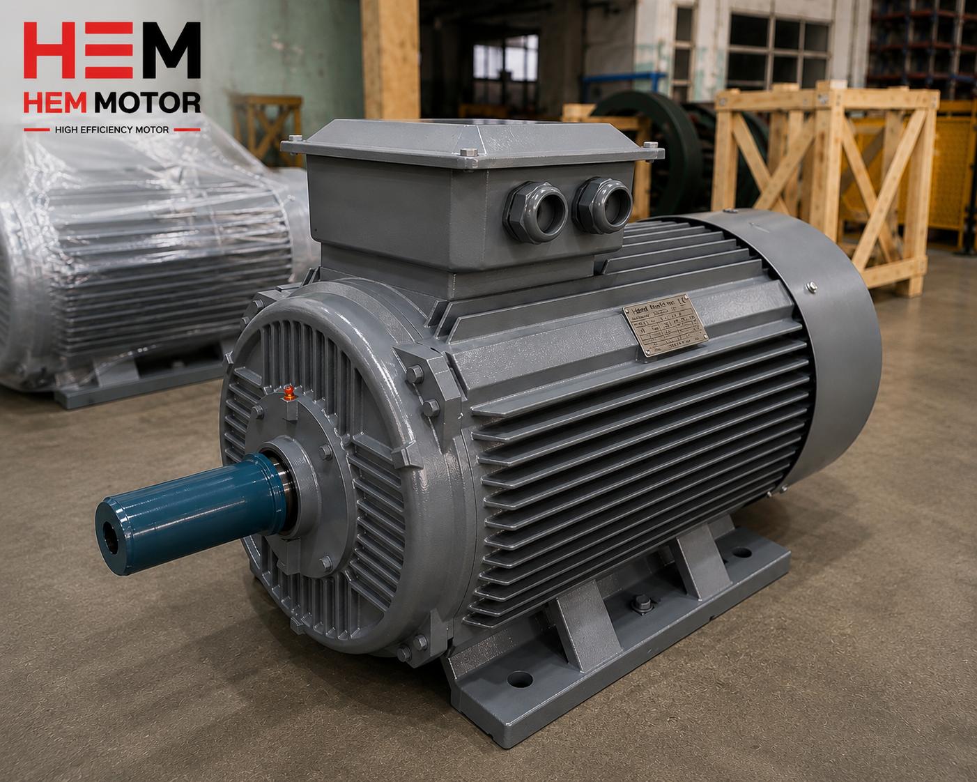
On a standard IEC motor there are two separate points for grounding. The first is the PE screw located inside the terminal box, next to the phase leads; this is where the protective conductor of the cable feeding the motor is connected. The second is the external grounding terminal located outside the motor frame, usually on the foot or body. The functions of these two terminals are different, and both are important.
Two Grounding Points: Why Are Both Needed?
At first glance a single grounding connection may seem enough; but standards (IEC 60034-1, IEC 60204-1) in most cases require or recommend two separate points:
- PE terminal inside the terminal box: Carries the protective conductor of the supply cable. It is the motor's main ground connection and returns the fault current to the panel through the supply cable.
- External PE terminal (outside the frame): Connects the motor frame to the plant's equipotential earth bar or machine chassis. This keeps the frame always at earth potential and prevents touch voltage from forming.
The two points work together: one is the main path for fault current, the other is a backup and equipotential safeguard. Even if the connection inside the terminal box loosens, the external terminal continues to keep the frame at earth potential. In VFD systems the external connection also discharges high-frequency leakage currents; we will detail this shortly.
Protective Conductor Cross-Section: How Thick Should It Be?
The cross-section of the PE conductor is not chosen at random; it is set by standard depending on the cross-section of the phase conductor. The general rule (IEC 60204-1 / IEC 60364-5-54) is: if the phase cross-section is small the PE equals the phase, at medium cross-sections a certain minimum, and at large cross-sections it may be half of the phase.
| Phase conductor cross-section S (mm²) | Minimum PE cross-section (mm²) | Typical external terminal bolt |
|---|---|---|
| S ≤ 16 | S (equal to phase) | M5 - M6 |
| 16 < S ≤ 35 | 16 | M6 - M8 |
| 35 < S ≤ 400 | S / 2 | M8 - M10 |
| S > 400 | S / 2 (min 200) | M10 - M12 |
The bolt sizes in the table are for guidance; they vary with the motor's power and terminal design. What matters is that the PE connection has a cross-section and tightness that can carry the fault current without overheating or loosening. To see cable, fuse and protection selection by rated current holistically, our article on rated current: cable, fuse and contactor selection is a good reference.
Equipotential Bonding: Equalising the Frame With Earth
Equipotential bonding means connecting all conductive bodies in a plant (motor, machine chassis, pipeline, steel structure) to each other and to earth so that no voltage difference forms between them. The motor's external PE terminal is part of this bonding network. The purpose is this: during a fault, no dangerous potential difference should form between the motor frame and another metal surface that can be touched.
Without bonding, even a small resistance difference between two separately grounded points can create touch voltage during a fault. A proper bonding network keeps this difference near zero. So the external PE terminal is not just "a wire to earth"; it is a node of the plant's equipotential safety network.
- Low resistance: The bonding conductor should be short and of suitable cross-section.
- Clean contact: Paint, rust and oxide must be cleaned from the connection point.
- Serrated washer / toothed surface: A serrated washer should be used for contact under paint.
- Tightness: The bolt must be tightened to proper torque, with a measure against loosening.
High-Frequency Grounding in a VFD System
On motors running with a frequency drive, grounding is not only a safety matter; it is also an EMC (electromagnetic compatibility) matter. The drive produces high-frequency leakage currents, and these currents need to return to ground via a low-impedance path. A grounding connection that is good at low frequency may be inadequate at high frequency; because a long, thin wire presents high impedance at high frequency.
So two things are critical in a VFD system: a shielded motor cable and 360° (all-around) grounding of the shield. The cable shield must be grounded all around with a special EMC gland or clamp, at the panel and at the motor, not by a single pigtail at one end. This offers the shortest and lowest-impedance path for the high-frequency current; it reduces both EMC interference and bearing-current risk. We covered this holistic approach in depth in our article on grounding and EMC: connection in a VFD system.
Inadequate high-frequency grounding also sets the stage for bearing-current damage. You can find its relationship with the shaft grounding ring and bearing-current protection in our article on bearing current and the shaft grounding ring.
| Grounding purpose | Connection point | Critical point |
|---|---|---|
| Safety (fault current) | PE inside terminal box + external terminal | Cross-section and tightness |
| Equipotential bonding | External PE terminal | Clean, low-resistance contact |
| EMC / high frequency | 360° shield grounding | Short path, all-around contact |
Frequently Asked Questions
Can I leave the motor's external grounding terminal unconnected?
No, it must be connected. The PE inside the terminal box carries the protective conductor of the supply cable; the external terminal connects the frame to the plant's equipotential earth network. They serve different functions, and for safety both are expected to be connected. The external connection also performs the task of discharging high-frequency currents in VFD systems.
What should I base the PE conductor cross-section on?
On the cross-section of the phase conductor. The general rule: up to 16 mm² the PE equals the phase, between 16-35 mm² at least 16 mm², and above 35 mm² half the phase. For the exact value, the plant standard and the trip value of the protective device should be checked. What matters is that the PE can carry the fault current without overheating.
If I use a VFD, isn't normal grounding enough?
Often it is not enough. A grounding that is good at low frequency may present high impedance for the high-frequency currents the drive produces. So a shielded cable and 360° grounding of the shield are needed; this is the most effective method for reducing both EMC interference and bearing-current risk.
The Working Logic of Grounding: What Happens During a Fault?
To understand why grounding is vital, let us follow an insulation fault step by step. The motor's winding insulation weakens due to ageing, moisture or overheating, and a phase conductor touches the frame. If the frame is not grounded, the frame is now at phase voltage; anyone touching it is shocked by the current flowing from their body to ground. If grounding is connected, the fault current flows through the PE conductor via a very low-resistance path; this high current blows the fuse or trips the breaker, and the circuit is cut within seconds.
For this mechanism to work, two conditions are required: the PE conductor must be thick enough (to carry the high fault current without overheating) and the earth loop impedance must be low enough (to allow the current that trips the protective device to flow). So grounding is not just running a wire; it is building a circuit through which the fault current flows safely and triggers the protective device. A wrong cross-section or a loose connection breaks this chain and the protection fails to act.
Terminal Hardware and Connection Quality
The physical quality of the PE connection is at least as important as the cross-section. The PE screw inside the terminal box and the external terminal outside the frame should be of corrosion-resistant materials such as brass, stainless or galvanised steel. If there is paint, rust or oxide at the connection point, the contact resistance rises and the fault current cannot flow properly. This is why a serrated washer that contacts under the paint is usually used on the external terminal.
- Cable lug: The PE conductor should be terminated with a suitable lug; bare wire should not be wrapped directly around the screw.
- Torque: The bolt should be tightened to the torque given by the manufacturer; under-tightening risks loosening, over-tightening risks stripping the thread.
- Anti-loosening measure: A spring washer or nut lock prevents loosening in a vibrating environment.
- Corrosion protection: Outdoors, the terminal must be protected against corrosion and checked periodically.
We addressed the importance of frame and terminal protection for motors running outdoors or in corrosive environments, in the context of cast iron frames, in our article on cast iron versus aluminium frame; the corrosion resistance of connection points directly affects the long-term reliability of grounding.
Terminal Box, IP Protection and Moisture
The terminal box where the PE connection is made must be protected from the outside environment. The IP protection class of the box prevents moisture and dust from entering; if moisture enters, there is a risk of corrosion and leakage current at both the phase connections and the PE contact. Suitable glands should be used at cable entries, and unused holes should be closed with blind plugs. In a humid or dusty environment, choosing the correct IP class is also part of grounding safety.
Where the motor is stored or runs in a humid environment, condensation can also cause problems inside the terminal box. You can find the relationship between storage, moisture and commissioning in our article on storage and long-term standing.
Checklist for Correct Grounding
- Connect the protective conductor of the supply cable to the PE screw inside the terminal box.
- Connect the external terminal outside the frame to the plant's equipotential earth bar.
- Choose the PE cross-section to standard according to the phase cross-section.
- Clean paint, rust and oxide from the contact surface; use a serrated washer.
- Tighten the bolts to proper torque and take a measure against loosening.
- In a VFD system, apply a shielded cable and 360° shield grounding.
A correct protective conductor connection is the motor's cheapest yet most valuable safety investment; during a fault, this connection is often the only thing protecting people and the plant. For motors with the right terminal hardware, cross-section and EMC-compliant grounding options, request a technical quotation from the HEM Motor team; standard and drive-compatible motors are delivered quickly from stock with suitable terminal box options.