English
 Türkçe

One of the most common and most critical checks when commissioning an IE3 efficient asynchronous motor in the field is the direction of rotation. A motor can be correctly wired, have sound insulation and a suitable nameplate, yet if the shaft turns the wrong way the pump delivers no water, the fan moves no air, the conveyor runs backwards, and in some applications mechanical damage begins within minutes. The direction of rotation is determined directly by the phase sequence (L1-L2-L3). In this article we explain the relationship between phase sequence and rotation direction in IE3 motors, how to reverse direction by swapping two phases, how to use a phase sequence meter, and why the wrong direction causes serious damage in pump and fan applications.
Relationship Between Phase Sequence and Rotation Direction
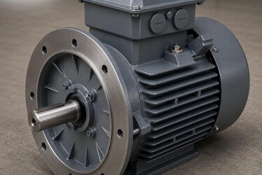
In a three-phase IE3 asynchronous motor, a rotating magnetic field is created in the stator. The direction of this rotating field depends on the sequence in which the three phases (L1, L2, L3) are connected to the motor terminals (U1, V1, W1). When the standard phase sequence is L1-L2-L3 and connected to U1-V1-W1 respectively, the motor typically rotates clockwise (CW) when viewed from the shaft (drive) end. IEC 60034-7 and IEC 60034-8 define the direction of rotation as seen from the shaft (D-end).
The most important rule is this: if any two of the three phases are swapped, the rotating magnetic field reverses and the shaft turns in the opposite direction. A motor running clockwise will run counter-clockwise (CCW) once you swap two phases (for example V1 and W1). This is a universal rule that applies to IE3 motors and to all three-phase asynchronous motors.
CW and CCW: Viewed From Which Side?
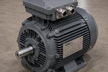
The most frequent mistake in defining rotation direction is failing to state the reference side. When you say "clockwise" in the field, it must be clear from which side the shaft is viewed. The accepted standard is to view from the drive end (shaft output, D-end). Viewed from this side, if the shaft turns clockwise it is CW, otherwise CCW. The direction arrow on the nameplate or frame shows the manufacturer's designed standard rotation, but this arrow is often related to the aerodynamic design of a unidirectional cooling fan and must always be confirmed at the order stage.
Reversing Direction by Swapping Two Phases
To reverse the direction of rotation there is no need to touch the motor windings; you only swap two phases on the supply side. In practice this is done in the motor terminal box or at the contactor output in the panel:
- If the existing connection is L1-U1, L2-V1, L3-W1,
- swapping phases L2 and L3 to L2-W1, L3-V1 reverses the direction.
- It does not matter which two phases are swapped; any two-phase swap reverses direction. Shifting all three phases circularly (L1-V1, L2-W1, L3-U1) does not change direction because the sequence is preserved.
In applications requiring forward-reverse (reversing) operation, this is automated with two contactors (a reversing contactor group). Mechanical and electrical interlocking that prevents both contactors from energizing simultaneously is mandatory; otherwise a phase-to-phase short circuit occurs. In reversing applications, the motor should also be allowed to stop (or a suitable delay defined) before reversing; forcing a spinning rotor to reverse with a sudden command causes very high current and mechanical shock.
Direction With Star-Delta and Softstarter
In star-delta starting, direction depends on the correct delta bridging and the supply phase sequence. Incorrect bridging can affect both direction and torque. In soft starters, the input phase sequence determines the output sequence; a soft starter does not reverse direction on its own. Our articles on star-delta vs softstarter starting and IE3 motor star/delta winding connection provide complementary detail.
Phase Sequence Meter (Rotation Tester)
The safe way to predict rotation direction without ever running the motor is to measure the supply phase sequence. A phase sequence indicator / rotation meter, connected to the three phases via three probes, shows whether the grid phase sequence is clockwise (L1-L2-L3, usually a right-rotation indication) or reversed. This device is especially used:
- in a new facility or generator supply where the phase sequence is unknown,
- to establish a standard phase sequence on lines where multiple motors must turn the same way,
- before first start of critical machines such as pumps and fans where the wrong direction causes damage.
Modern devices also include contactless models; however, a contact-probe type gives a more precise result for panel measurement. After verifying the phase sequence, the motor is jogged briefly to confirm shaft direction visually. Our motor commissioning and first startup checklist guides this step by step.
Damage From Wrong Rotation Direction: Pumps and Fans
The wrong direction does not produce the same result in every application; in some machines only efficiency drops, while in others serious mechanical damage occurs.
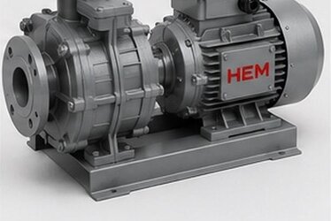
In Centrifugal Pumps
If the impeller of a centrifugal pump turns in reverse, the pump may deliver some water but its flow and head stay far below rated values; because the motor runs at low load the fault may not be noticed immediately. More dangerously, in some pumps the impeller nut tightens with the direction of rotation; the reverse direction can loosen the impeller, and the impeller may separate from the shaft and damage the volute. In deep-well and submersible pumps, the wrong direction leads to cavitation and overheating. For pump motor selection criteria see centrifugal pump motor selection and deep-well pump motor selection.
In Fans and Aspirators
The wrong direction is especially misleading in axial and radial fans. When a backward-curved radial fan runs in reverse, the airflow may still be in the same direction but the flow drops greatly and the fan runs far less efficiently; the operator thinks the fan "works" but the desired ventilation is not achieved. In axial fans, reverse rotation can completely reverse the air direction. For fan motors, our articles on centrifugal and axial fan motor selection and aspirator and dust collection fan motor selection detail the importance of direction control.
Conveyors and Other Drives
In conveyor belts the wrong direction moves material the wrong way and causes mechanical jamming in some scraper and flap systems. In geared drives, while reverse direction may not cause issues in some self-locking worm gear systems, in helical and bevel gear reducers the direction must be chosen to suit the application. Our article on conveyor belt motor replacement is useful here.
Rotation Direction Check Steps at Commissioning
The sequence to safely verify rotation direction at first start of an IE3 motor:
- Read the direction arrow on the nameplate and frame; confirm the required direction from the machine manufacturer's instructions.
- Measure the supply phase sequence with a phase sequence meter.
- Decouple the motor from the load, or make sure it is safe for the pump/fan; jog the shaft briefly.
- Check direction visually by looking at the shaft from the drive end.
- If wrong, disconnect supply, swap two phases in the panel and re-test.
- Once correct, monitor the motor under load for current and vibration.
For incoming and acceptance checks, our incoming and acceptance inspection (megger, rotation, vibration) article provides a standard stock-entry procedure. For order notes on phase sequence and direction, our motor rotation direction and phase sequence article is complementary.
Rotation Direction and Efficiency in IE3 Motors
IE3 class motors have a magnetic design optimized for high efficiency; however, the direction of rotation does not change the efficiency class. Direction relates only to suitability for the application. That said, in IE3 motors with a forced-cooling fan or special blades designed for one direction, reverse rotation can impair cooling and overheat the motor. Therefore, to preserve the efficiency and life of an IE3 motor, the correct direction must be confirmed at first start. For general features of IE3 motors see reading the IE3 motor nameplate and IE3 motor stock guide. For the product family, explore our IE3 efficient electric motors category, and for a general start visit our electric motors section.
The Physics of the Three-Phase Rotating Field and Direction Logic
To truly grasp rotation direction, you need to understand how the rotating magnetic field is formed. The windings of a three-phase stator are placed 120 degrees apart in space, and each phase is fed current also shifted 120 degrees in time. The combination of the positional difference in space and the phase difference in time produces a magnetic field in the stator with constant amplitude but continuously rotating. The rotation direction of this field depends on the order in which the phases are "fired" into the stator windings. If L2 follows L1, then L3, the field turns one way; if L3 follows L1, then L2, it turns the other way. Swapping two phases reverses exactly this timing order, and that is why the direction changes.
The rotor follows this rotating field with a slight lag (slip); that is why the actual speed of an asynchronous motor is slightly below synchronous speed. For the slip and actual-speed relationship, our slip and actual speed article completes the topic. Keep in mind that rotation direction does not change the rotor's slip behavior; it only determines the direction of the field it follows. The efficiency curve and magnetic design of an IE3 motor are the same in both directions; apart from a unidirectional cooling fan, direction does not affect electrical performance.
Unidirectional Cooling Fan and Direction Dependence
The cooling fan behind an IE3 motor is usually designed bidirectional (radial blades); these fans deliver roughly the same airflow in both directions and cool the motor. However, some high-efficiency or special motors use a unidirectional (angled-blade) cooling fan to reduce friction and windage loss. If such a motor is run in reverse, the fan moves far less air, the motor cannot cool and overheats under continuous load. Therefore, on motors with a unidirectional fan, the direction arrow on the frame is not just a suggestion but a requirement.
Clarifying at the order stage whether the motor has a bidirectional or unidirectional fan is important to avoid surprises if a direction change is needed later. For cooling methods and the effect of fan design on efficiency, see our cooling methods (IC411/IC416) article. The correct direction should not be overlooked even on a quality motor for the sake of heating and life, because a drop in cooling raises winding temperature and shortens insulation life.
Panel Design in Reversing (Forward-Reverse) Applications
Some machines must by nature run in two directions: crane and hoist raise-lower, some door and barrier systems, forward-reverse feed tables. In these applications the direction change is automatic and panel design becomes critical. Two contactors are used; one makes the forward connection (e.g. L1-U1, L2-V1, L3-W1) and the other the reverse (two phases swapped). These two contactors must never energize at the same time; otherwise a direct short circuit occurs between two phases. Therefore:
- Mechanical interlock: the contactors are physically interlocked to prevent both from pulling in.
- Electrical interlock: the auxiliary contact of each contactor cuts the coil circuit of the other.
- Software/time delay: a short wait (dead time) is inserted at direction change; the spinning rotor is allowed to slow down.
In braked and lifting applications such as cranes, direction control is part of safety; our crane and hoist lifting motors article is complementary here. In systems using a frequency drive (VFD), direction can be changed in software with a drive parameter; in that case no physical phase swap is needed, but the drive's smooth direction-change ramp must be set correctly. See VFD with asynchronous motor.
Typical Mistakes Made in the Field
The most common mistakes in rotation direction control in the field are: failing to clarify which side the direction arrow is viewed from; running a pump or fan in the wrong direction under load for a long time and causing damage; shifting all three phases and being surprised that "direction did not change" (because circular shifting does not change direction); and ignoring that a generator supply may have a different phase sequence than the grid. Especially on lines where multiple motors are fed from the same panel, if a standard phase sequence is not established, some motors may turn correctly and others in reverse. To prevent these mistakes, a written commissioning procedure and phase sequence measurement should be made standard. For general commissioning mistakes, our mistakes made when buying an electric motor article is also useful.
Frequently Asked Questions
How many phases must I change to reverse the motor direction?
Only two. When any two of the three phases are swapped, the rotating magnetic field reverses and the shaft turns the opposite way. Shifting all three phases circularly does not change direction.
Can I determine direction without a phase sequence meter?
You can jog the motor briefly and look at the shaft from the drive end to see the direction. However, for machines such as pumps and fans where the wrong direction causes damage, verifying the supply with a phase sequence meter before running is much safer.
Will the motor be damaged if the pump runs in reverse?
The motor itself is usually not damaged while turning in reverse; the real risk is in the pump (loosening impeller nut, cavitation, low flow) and overheating in some unidirectionally cooled motors. Therefore direction must always be verified at first start.
Get a Quote
Contact us for support with the rotation direction, phase connection and application-correct selection of your IE3 efficient motor. Our expert team ensures fast supply with the right frame, speed and connection type. Request a quote on +90 (532) 345 49 86 or via our contact page.
Rotation Direction and Phase Sequence Checklist (Purchasing and Commissioning)
- Determine the rotation direction required by the machine manufacturer (CW/CCW, from the drive end).
- Confirm the direction arrow on the nameplate and frame at the order stage.
- Ask whether the motor has a unidirectional cooling fan/special blades or is bidirectional.
- If forward-reverse operation is required, plan an interlocked contactor group.
- Verify the supply with a phase sequence meter before commissioning.
- Jog to check direction at first start; if wrong, swap two phases.
- Monitor current, vibration and temperature in the correct direction.